|
|
Battery Terminal Cleaning Tools The red tool looks cheaper, but it actually works much better than the all-metal version because its edges stay sharper. Both are designed to reshape damaged lead terminals, but the all-metal one doesn't have enough spring pressure for the post cleaners, and has only 1 cutting edge on each post cleaner. Since they're rigid, those don't work as well on hard terminals as the plumber's brush style, so use it on steel or copper terminals, or lead terminals with deep pitting. If these aren't enough, replace the terminals as described in the next several captions. See also:  .  .  .  .  .  . 
|
|
|
These are the absolute crappiest terminals on the market, and they're becoming the most-popular. The wires are (supposed to be) clamped into a serrated channel in the lead, but if the wire is too thin, there's not enough clamping force. And if there's too much wire (like this), the straps bend & weaken, reducing the clamping force. Also, with all the pockets & threads, they collect acid, causing rapid corrosion. And like all lead terminals, they stretch over time, even if they're not overtightened. But they're ALWAYS overtightened. And that paint that makes them so popular is another BIG problem: it's usually allowed to coat both the wire channel AND the hole for the post, causing a poor connection in 2 places, even when new & clean. The connections only get worse as it ages. These were installed less than a month ago, and they've already failed (on Christmas day) which is why I'm replacing them today with solder-on terminals. Here's someone else's pic of a similar terminal: 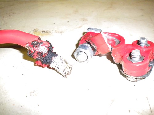 Note that the interior bore is almost completely coated with highly-insulative PAINT, and that's probably the same reason the cable got hot enough to melt its insulation - paint in the cable pocket. See also: . 
|
|
|
Late-Model OE-style Battery Terminals ~$10ea @ NAPA The "lead-free" description is misleading. The other solder-on terminals are also lead-free; they're brass or copper with a tin or silver-solder coating. But this style may be a better fix if the damaged terminal is this style since it can merely be unbolted & replaced (no soldering) if the original ring terminals are undamaged. If these new ring terminals must be soldered on, the wires should be cleaned & tinned (coated with fresh solder) first. Then these rings can be crimped on & soldered to the tinned wires, but that prevents them from ever being removed/reused. See also: . . . . . Motorcraft F2TZ-14301-B Negative Battery Cable with body, frame, & block grounds
|
|
|
Q: "Why do I have battery problems?" A: Why wouldn't you? Any ONE of these can cause slow cranking, starter damage, starter relay damage, starter cable damage, alternator damage or malfunction, low voltage, random spurious fault codes, driveability issues, winch/inverter malfunctions... The rest of this photo album shows the CORRECT way to replace these terminals. Look for PREV/NEXT at the top Left of this page, or click the album name links, or just keep scrolling down if you're already viewing the whole album. See also: .  . . . . . Motorcraft F2TZ-14301-B Negative Battery Cable with body, frame, & block grounds http://www.batteryfaq.org/
|
|
|
Battery Brands Choose wisely. A few extra dollars up front can be a lot cheaper in the long run. The top 2 are the best batteries for the money. ~$120 (in 2020, during sales) with an 8-year warranty, the first 3 of which are free-replacement. The Optima doesn't come close to that, or the CCA or reserve capacity, and costs MUCH more. MotorCraft & Interstate are made by Johnson Controls, just like Optima, but they're from the same line as Sears DieHard Gold and a few other high-quality batteries. DuraLast & EverStart are bottom-end JC batteries. Before buying a craptasmic battery or other common part, check for coupons & service offers from Ford.  .  .  .  . http://www.batteryfaq.org/
|
|
|
This one of the reasons why some batteries cost more: their cases are molded better around the lead posts, creating a better seal. These leak acid around the posts, corroding the vehicle's terminals, bodies, and everything else. http://www.batteryfaq.org/
|
|
|
Before hammering the terminal down onto the battery post, remove its bolt (especially if it's very difficult to remove) and spread the terminal until it can drop all the way to the BOTTOM of the post without effort. Make sure the bolt hole is clean (drill it if necessary), and apply a thin layer of electrical grease (NOT dielectric, chassis, or thermal greases, or anti-seize, or red battery-spray slime) to the entire terminal & inside the bolt holes, including any exposed wire strands. When tightening the bolt, use a tool to prevent its square head from turning against the lead terminal's stop. ONLY tighten the bolt enough to prevent the terminal from rotating on the post by hand. The MotorCraft TestedToughMAX is the best battery on the market, with the best warranty (particularly if you pay a Ford dealership to install it). It's among the most-expensive, but it's worth it, especially if you buy when there's a sale. Check here for coupons & service offers from Ford.
|
|
|
For whatever reasons (corrosion, overtightening, poorly-attached accessories...), automotive battery terminals often need to be replaced. This one was damaged by the winch ground wire clamped to its side. The terminal developed minor corrosion, which raised the resistance enough to cause a severe power loss during the high-current load applied by the winch motor. This power loss heated the Lead terminal to melting, and the liquid Lead ran down onto the plastic battery case. Fortunately, the molten Lead didn't penetrate, and the terminal maintained enough integrity to continue to function enough for the vehicle to remain operable. But without the clamping force applied by the bolt, the terminal is losing contact with the battery post, resulting in low voltage to the vehicle. Clamp-on battery terminals are very common, but they result in another poor connection which will likely have this same result (or worse). So a soldered connection is preferred. Crimp-on battery terminals are available, and commonly used as OE. But the crimpers are expensive and hard-to-find. And a crimped joint doesn't self-seal like a full solder joint. Additionally, if a battery terminal overheats with a solder joint, the solder will melt, probably disconnecting the battery before further damage occurs. A crimped joint won't release, and the battery may explode or catch fire. Finally, crimped terminals can't be repaired in the field, and can never have additional wires added in, like solder terminals can. So soldered-on terminals are inherently better & more user-friendly. See also: . . . Motorcraft F2TZ-14301-B Negative Battery Cable with body, frame, & block grounds ___________________________________________________ "Grounding" is commonly misunderstood... When electricity first became publicly available (when Edison & Tesla were fighting over DC vs. AC), Copper wire was very expensive. So rather than run 2 wires everywhere, Tesla realized he could run a "hot" wire, and then use the ground (the actual dirt of the Earth) as the return circuit path. (He also thought he could use the ionosphere as the hot side, but he never got that to work.) Inside a house, there still had to be 2 wires, but one of them went "to the ground" via a Copper rod driven into the dirt outside the house. That became known as "the ground wire". When vehicles acquired electric circuits (AFAIK, the first on any Ford was the electric horn, which Ford always numbers as circuit #1), it was equally-efficient to use the metal chassis of the vehicle as one the main electrical pathways, to reduce the amount of wire needed. And the term "ground" was carried over into that arena. Chassis grounding worked reasonably-well until alternators got up into the ~100A range (in the 80s) and vehicle wiring harnesses began to exceed the weight of the drivetrain (AFAIK, the first to cross that line was the '92 Lincoln Continental V6). Since then, more circuits are networked through high-speed data bus lines via communication modules so that you don't need a discrete wire running from one end of the vehicle to the other & another coming back to turn on a taillight, and confirm that the bulb isn't burnt out. But as a result, the chassis/body ground is no longer sufficient to provide a reliable circuit path without introducing a lot of background noise (RFI) into those minuscule high-frequency data signals. So the trend for a couple of decades now has been to run actual Copper return wires so that far less current flows through the chassis steel. (House wiring standards added a return "neutral" wire decades before that.) So by definition, if you're using a wire to return to the battery, you're not "grounding" that circuit - you're wiring it. And wiring it is a good idea when you're dealing with rusty 40- to 50-year-old body & frame steel. The catch is that the return wiring has to be AT LEAST as large as ALL the power wiring that it serves - IOW, very big like the alternator output wire, the starter wire, the winch wiring, and the ignition switch battery-supply wires. None of it needs to be bigger than the battery cables because you can't ever get more current flowing than the battery can put out (roughly whatever its CA rating is). So if you want to be sure you have a good return path throughout any vehicle, just extend the battery (-) cable all the way to the trailer connector. Obviously, you can't run a cable that big into the trailer connector or anything else - you have to splice onto it to branch off with smaller black wire (or whatever color the particular circuit uses for "ground"). That's why I refer to that as a "trunk ground" system - the main return wire is like a big tree trunk, with the variously-sized smaller branches shooting out to hit each point on the vehicle that needs an exceptionally-reliable return (generally: the high-current devices; and those that require low RFI noise, like audio amplifiers). Fortunately, those splices DON'T need to be insulated - they can be left showing bare metal. Copper & solder don't corrode very quickly in air, or even in common rainwater. Mainly just at the battery where acid leaks out. Road salt will eventually cause some corrosion, but probably not enough to matter within the remaining lifespan of even the best-maintained antiques. And the body & frame should still be GROUNDED at a few points, just to reduce galvanic corrosion, and to serve the very-low-current chassis-grounded loads like taillights & fuel level senders.
|
|
|
Fortunately, the Lead terminal didn't melt into the Lead battery post, and the battery wire is virtually undamaged. But even if it were, it's fairly simple & quick to straighten out & clean the strands of wire to make a quick, secure, & reliable solder joint. See also: . . . Motorcraft F2TZ-14301-B Negative Battery Cable with body, frame, & block grounds
|
|
|
This terminal appears to be in fair condition for its age, but I'm replacing the other anyway, so this one is coming off. Motorcraft F2TZ-14301-B Negative Battery Cable with body, frame, & block grounds ___________________________________________________ "Grounding" is commonly misunderstood... When electricity first became publicly available (when Edison & Tesla were fighting over DC vs. AC), Copper wire was very expensive. So rather than run 2 wires everywhere, Tesla realized he could run a "hot" wire, and then use the ground (the actual dirt of the Earth) as the return circuit path. (He also thought he could use the ionosphere as the hot side, but he never got that to work.) Inside a house, there still had to be 2 wires, but one of them went "to the ground" via a Copper rod driven into the dirt outside the house. That became known as "the ground wire". When vehicles acquired electric circuits (AFAIK, the first on any Ford was the electric horn, which Ford always numbers as circuit #1), it was equally-efficient to use the metal chassis of the vehicle as one the main electrical pathway, to reduce the amount of wire needed. And the term "ground" was carried over into that arena. Chassis grounding worked reasonably-well until alternators got up into the ~100A range (in the 80s) and vehicle wiring harnesses began to exceed the weight of the drivetrain (AFAIK, the first to cross that line was the '92 Lincoln Continental V6). Since then, more circuits are networked through high-speed data bus lines via communication modules so that you don't need a discrete wire running from one end of the vehicle to the other & another coming back to turn on a taillight, and confirm that the bulb isn't burnt out. But as a result, the chassis/body ground is no longer sufficient to provide a reliable circuit path without introducing a lot of background noise (RFI) into those minuscule high-frequency data signals. So the trend for a couple of decades now has been to run actual Copper return wires so that far less current flows through the chassis steel. (House wiring standards added a return "neutral" wire decades before that.) So by definition, if you're using a wire to return to the battery, you're not "grounding" that circuit - you're wiring it. And wiring it is a good idea when you're dealing with rusty 40- to 50-year-old body & frame steel. The catch is that the return wiring has to be AT LEAST as large as ALL the power wiring that it serves - IOW, very big like the alternator output wire, the starter wire, the winch wiring, and the ignition switch battery-supply wires. None of it needs to be bigger than the battery cables because you can't ever get more current flowing than the battery can put out (roughly whatever its CA rating is). So if you want to be sure you have a good return path throughout any vehicle, just extend the battery (-) cable all the way to the trailer connector. Obviously, you can't run a cable that big into the trailer connector or anything else - you have to splice onto it to branch off with smaller black wire (or whatever color the particular circuit uses for "ground"). That's why I refer to that as a "trunk ground" system - the main return wire is like a big tree trunk, with the variously-sized smaller branches shooting out to hit each point on the vehicle that needs an exceptionally-reliable return (generally: the high-current devices; and those that require low RFI noise, like audio amplifiers). Fortunately, those splices DON'T need to be insulated - they can be left showing bare metal. Copper & solder don't corrode very quickly in air, or even in common rainwater. Mainly just at the battery where acid leaks out. Road salt will eventually cause some corrosion, but probably not enough to matter within the remaining lifespan of even the best-maintained antiques. And the body & frame should still be GROUNDED at a few points, just to reduce galvanic corrosion, and to serve the very-low-current chassis-grounded loads like taillights & fuel level senders.
|
|
|
This shows how little of the wire is actually in contact with the lead terminal, and how much room there is inside the terminal to hold acid & corrosion. I've actually found much-newer much-cleaner-looking cables in much-worse condition inside; so bad that they had intermittent cranking failures. Motorcraft F2TZ-14301-B Negative Battery Cable with body, frame, & block grounds ___________________________________________________ "Grounding" is commonly misunderstood... When electricity first became publicly available (when Edison & Tesla were fighting over DC vs. AC), Copper wire was very expensive. So rather than run 2 wires everywhere, Tesla realized he could run a "hot" wire, and then use the ground (the actual dirt of the Earth) as the return circuit path. (He also thought he could use the ionosphere as the hot side, but he never got that to work.) Inside a house, there still had to be 2 wires, but one of them went "to the ground" via a Copper rod driven into the dirt outside the house. That became known as "the ground wire". When vehicles acquired electric circuits (AFAIK, the first on any Ford was the electric horn, which Ford always numbers as circuit #1), it was equally-efficient to use the metal chassis of the vehicle as one the main electrical pathway, to reduce the amount of wire needed. And the term "ground" was carried over into that arena. Chassis grounding worked reasonably-well until alternators got up into the ~100A range (in the 80s) and vehicle wiring harnesses began to exceed the weight of the drivetrain (AFAIK, the first to cross that line was the '92 Lincoln Continental V6). Since then, more circuits are networked through high-speed data bus lines via communication modules so that you don't need a discrete wire running from one end of the vehicle to the other & another coming back to turn on a taillight, and confirm that the bulb isn't burnt out. But as a result, the chassis/body ground is no longer sufficient to provide a reliable circuit path without introducing a lot of background noise (RFI) into those minuscule high-frequency data signals. So the trend for a couple of decades now has been to run actual Copper return wires so that far less current flows through the chassis steel. (House wiring standards added a return "neutral" wire decades before that.) So by definition, if you're using a wire to return to the battery, you're not "grounding" that circuit - you're wiring it. And wiring it is a good idea when you're dealing with rusty 40- to 50-year-old body & frame steel. The catch is that the return wiring has to be AT LEAST as large as ALL the power wiring that it serves - IOW, very big like the alternator output wire, the starter wire, the winch wiring, and the ignition switch battery-supply wires. None of it needs to be bigger than the battery cables because you can't ever get more current flowing than the battery can put out (roughly whatever its CA rating is). So if you want to be sure you have a good return path throughout any vehicle, just extend the battery (-) cable all the way to the trailer connector. Obviously, you can't run a cable that big into the trailer connector or anything else - you have to splice onto it to branch off with smaller black wire (or whatever color the particular circuit uses for "ground"). That's why I refer to that as a "trunk ground" system - the main return wire is like a big tree trunk, with the variously-sized smaller branches shooting out to hit each point on the vehicle that needs an exceptionally-reliable return (generally: the high-current devices; and those that require low RFI noise, like audio amplifiers). Fortunately, those splices DON'T need to be insulated - they can be left showing bare metal. Copper & solder don't corrode very quickly in air, or even in common rainwater. Mainly just at the battery where acid leaks out. Road salt will eventually cause some corrosion, but probably not enough to matter within the remaining lifespan of even the best-maintained antiques. And the body & frame should still be GROUNDED at a few points, just to reduce galvanic corrosion, and to serve the very-low-current chassis-grounded loads like taillights & fuel level senders.
|
|
|
This terminal is about to fail for a variety of reasons, and that exposed wire isn't doing great.
|
|
|
Internally, it's even more corroded than the negative terminal shown before. . 
|
|
|
As bad as this looks, it CAN be cleaned & repaired without losing much of the cables' length. The wire can be untwisted & brushed to release the corrosion & then cleaned down to the good copper. Any remaining corrosion will be sealed inside the solder, so without water or oxygen, it can't do any more damage.
|
|
|
After cutting off the damaged terminal & stripping the cable slightly less than the depth of the replacement terminal, some corrosion within the strands is visible. After removing any grease & oil with brake cleaner (etc.), the strands can be brushed or scraped clean. It may be necessary to flatten the bundle in various directions to expose the corrosion for thorough cleaning. The terminal I'm using is a negative 2/0 from Carquest (BP96) and is specifically sized for the negative post (note the N debossed into it). The corresponding positive is BP95, and they were ~$7ea in 2009. The NAPA equivalents are 728014 (pos) & 728015 (neg) ~$9ea. Other sizes are available to accomodate more or less wire in the socket. They're cheaper online, but shipping must be considered. See also: . Motorcraft F2TZ-14301-B Negative Battery Cable with body, frame, & block grounds
|
|
|
The strands are now shiny clean, and the cable has been pre-bent the way it will need to be after the terminal is installed & attached to the battery. Additionally, there is enough slack in the cable to allow the bare end to naturally rest pointing straight DOWN at a location easily accessible with the torch. With the wire(s) pointing down, the battery terminal socket will point up, so the liquid solder won't run out. Motorcraft F2TZ-14301-B Negative Battery Cable with body, frame, & block grounds
|
|
|
The cable (along with any other wires to be attached) has been set in position in the new terminal, and positioned so that it is accessible for the torch, and so that the heat will not damage any surrounding components. In this case, I'm using the yellow-handled cutter's heavy blades as a heat sink to protect the plastic battery case. Any solder or rosin that escapes will be easy to clean off the cold pliers. See also: . Motorcraft F2TZ-14301-B Negative Battery Cable with body, frame, & block grounds ___________________________________________________ "Grounding" is commonly misunderstood... When electricity first became publicly available (when Edison & Tesla were fighting over DC vs. AC), Copper wire was very expensive. So rather than run 2 wires everywhere, Tesla realized he could run a "hot" wire, and then use the ground (the actual dirt of the Earth) as the return circuit path. (He also thought he could use the ionosphere as the hot side, but he never got that to work.) Inside a house, there still had to be 2 wires, but one of them went "to the ground" via a Copper rod driven into the dirt outside the house. That became known as "the ground wire". When vehicles acquired electric circuits (AFAIK, the first on any Ford was the electric horn, which Ford always numbers as circuit #1), it was equally-efficient to use the metal chassis of the vehicle as one the main electrical pathway, to reduce the amount of wire needed. And the term "ground" was carried over into that arena. Chassis grounding worked reasonably-well until alternators got up into the ~100A range (in the 80s) and vehicle wiring harnesses began to exceed the weight of the drivetrain (AFAIK, the first to cross that line was the '92 Lincoln Continental V6). Since then, more circuits are networked through high-speed data bus lines via communication modules so that you don't need a discrete wire running from one end of the vehicle to the other & another coming back to turn on a taillight, and confirm that the bulb isn't burnt out. But as a result, the chassis/body ground is no longer sufficient to provide a reliable circuit path without introducing a lot of background noise (RFI) into those minuscule high-frequency data signals. So the trend for a couple of decades now has been to run actual Copper return wires so that far less current flows through the chassis steel. (House wiring standards added a return "neutral" wire decades before that.) So by definition, if you're using a wire to return to the battery, you're not "grounding" that circuit - you're wiring it. And wiring it is a good idea when you're dealing with rusty 40- to 50-year-old body & frame steel. The catch is that the return wiring has to be AT LEAST as large as ALL the power wiring that it serves - IOW, very big like the alternator output wire, the starter wire, the winch wiring, and the ignition switch battery-supply wires. None of it needs to be bigger than the battery cables because you can't ever get more current flowing than the battery can put out (roughly whatever its CA rating is). So if you want to be sure you have a good return path throughout any vehicle, just extend the battery (-) cable all the way to the trailer connector. Obviously, you can't run a cable that big into the trailer connector or anything else - you have to splice onto it to branch off with smaller black wire (or whatever color the particular circuit uses for "ground"). That's why I refer to that as a "trunk ground" system - the main return wire is like a big tree trunk, with the variously-sized smaller branches shooting out to hit each point on the vehicle that needs an exceptionally-reliable return (generally: the high-current devices; and those that require low RFI noise, like audio amplifiers). Fortunately, those splices DON'T need to be insulated - they can be left showing bare metal. Copper & solder don't corrode very quickly in air, or even in common rainwater. Mainly just at the battery where acid leaks out. Road salt will eventually cause some corrosion, but probably not enough to matter within the remaining lifespan of even the best-maintained antiques. And the body & frame should still be GROUNDED at a few points, just to reduce galvanic corrosion, and to serve the very-low-current chassis-grounded loads like taillights & fuel level senders.
|
|
|
The essence of soldering is: 1) clean surfaces 2) all parts heated above the melting point of the solder (regardless if it's by flame or electric soldering iron) but not hot enough to cause flash-corrosion (heat-discoloration) 3) the correct solder & flux for the surfaces involved (rosin-core for Copper/electrical work) Also, given the size of the cable involved, proper position is important. The solder may wick up into the stranded cable & solidify, making it impossible to bend later. So it has been pre-bent & the terminal oriented to the bend so that it will be easy to install later. In addition to the main battery cable being soldered, I'm also connecting a smaller body ground wire, and a few extra wires for future circuits. The torch flame is set VERY low, and is aimed at a heavy area of the terminal to maximize the heat transferred from the flame into the metal. It's also worth considering where the flame's heat column will go so that the wire's insulation & surrounding parts aren't unnecessarily scorched. Initially, only the terminal is being heated. As it reaches the solder's melting temperature, the solder liquefies & flows around the wires inside the socket. Eventually, this brings the wires up to the melting temperature, and everything wets with solder making an exceptionally strong & conductive joint. If the solder appears slow to melt or the solder strand sticks to the terminal, it indicates insufficient heat in the joint. Cold solder joints are poor conductors, and are far more likely to fail mechanically (wires dropping out). But if the solder remains liquid for a few seconds after the heat source is removed, it indicates the temperature was appropriate. For this job, I used ~12" from a spool of Oatey brand Lead-Free (95% Tin; 5% Antimony) Rosin-Core Electrical Solder. But wherever solder-on battery terminals are sold, solder pellets are usually available. Pellets are typically NOT cost-effective compared to bulk solder spools, and they rarely fill the terminal socket. See also: . . Motorcraft F2TZ-14301-B Negative Battery Cable with body, frame, & block grounds
|
|
|
Note that the solder totally fills the socket, and the heat was maintained long enough for some solder to wick up into the strands of all the wires. These will effectively seal the joint, making it far less susceptible to contamination by battery acid that may leak out around the post, even without weatherproof heat-shrink tubing. After the solder solidifies, it can be splashed with water to cool & clean it. The brown stain is the excess rosin from inside the solder's core. With a little more care & a short section of large heat-shrink tubing, this could be made to look better than factory. But since this is my beater truck, and this connection is as functional & durable as any, I don't care how it looks. See also: . Motorcraft F2TZ-14301-B Negative Battery Cable with body, frame, & block grounds ___________________________________________________ "Grounding" is commonly misunderstood... When electricity first became publicly available (when Edison & Tesla were fighting over DC vs. AC), Copper wire was very expensive. So rather than run 2 wires everywhere, Tesla realized he could run a "hot" wire, and then use the ground (the actual dirt of the Earth) as the return circuit path. (He also thought he could use the ionosphere as the hot side, but he never got that to work.) Inside a house, there still had to be 2 wires, but one of them went "to the ground" via a Copper rod driven into the dirt outside the house. That became known as "the ground wire". When vehicles acquired electric circuits (AFAIK, the first on any Ford was the electric horn, which Ford always numbers as circuit #1), it was equally-efficient to use the metal chassis of the vehicle as one the main electrical pathway, to reduce the amount of wire needed. And the term "ground" was carried over into that arena. Chassis grounding worked reasonably-well until alternators got up into the ~100A range (in the 80s) and vehicle wiring harnesses began to exceed the weight of the drivetrain (AFAIK, the first to cross that line was the '92 Lincoln Continental V6). Since then, more circuits are networked through high-speed data bus lines via communication modules so that you don't need a discrete wire running from one end of the vehicle to the other & another coming back to turn on a taillight, and confirm that the bulb isn't burnt out. But as a result, the chassis/body ground is no longer sufficient to provide a reliable circuit path without introducing a lot of background noise (RFI) into those minuscule high-frequency data signals. So the trend for a couple of decades now has been to run actual Copper return wires so that far less current flows through the chassis steel. (House wiring standards added a return "neutral" wire decades before that.) So by definition, if you're using a wire to return to the battery, you're not "grounding" that circuit - you're wiring it. And wiring it is a good idea when you're dealing with rusty 40- to 50-year-old body & frame steel. The catch is that the return wiring has to be AT LEAST as large as ALL the power wiring that it serves - IOW, very big like the alternator output wire, the starter wire, the winch wiring, and the ignition switch battery-supply wires. None of it needs to be bigger than the battery cables because you can't ever get more current flowing than the battery can put out (roughly whatever its CA rating is). So if you want to be sure you have a good return path throughout any vehicle, just extend the battery (-) cable all the way to the trailer connector. Obviously, you can't run a cable that big into the trailer connector or anything else - you have to splice onto it to branch off with smaller black wire (or whatever color the particular circuit uses for "ground"). That's why I refer to that as a "trunk ground" system - the main return wire is like a big tree trunk, with the variously-sized smaller branches shooting out to hit each point on the vehicle that needs an exceptionally-reliable return (generally: the high-current devices; and those that require low RFI noise, like audio amplifiers). Fortunately, those splices DON'T need to be insulated - they can be left showing bare metal. Copper & solder don't corrode very quickly in air, or even in common rainwater. Mainly just at the battery where acid leaks out. Road salt will eventually cause some corrosion, but probably not enough to matter within the remaining lifespan of even the best-maintained antiques. And the body & frame should still be GROUNDED at a few points, just to reduce galvanic corrosion, and to serve the very-low-current chassis-grounded loads like taillights & fuel level senders.
|
|
|
The cooled & wire-brushed terminal is now installed on the cleaned battery post, making a connection that will last for years with no further maintenance. The clamp bolt is tightened ONLY enough to prevent the terminal from being twisted on the battery post by hand. Although this terminal's copper construction makes it MUCH stronger than a lead terminal, it can still be damaged by overtightening. Overtightening is merely a compensation for a poor connection, and this one is already as good as can be had. Grease & sprays are not necessary, and will not make the joint more reliable. But the correct grease would be Electrical Grease such as MotorCraft XG-12 (NOT dielectric, thermal, chassis, white lithium, anti-seize, or red slime battery spray). Attaching the winch ground cable as shown is NOT ideal, but I haven't decided yet how to route the cables. Since solder is easy to melt & reattach, this is NOT the permanent arrangement. Finally, check the ALTERNATOR, frame, & block ground connections, as described here:  .  .  . . See also: . . . . Motorcraft F2TZ-14301-B Negative Battery Cable with body, frame, & block grounds ___________________________________________________ "Grounding" is commonly misunderstood... When electricity first became publicly available (when Edison & Tesla were fighting over DC vs. AC), Copper wire was very expensive. So rather than run 2 wires everywhere, Tesla realized he could run a "hot" wire, and then use the ground (the actual dirt of the Earth) as the return circuit path. (He also thought he could use the ionosphere as the hot side, but he never got that to work.) Inside a house, there still had to be 2 wires, but one of them went "to the ground" via a Copper rod driven into the dirt outside the house. That became known as "the ground wire". When vehicles acquired electric circuits (AFAIK, the first on any Ford was the electric horn, which Ford always numbers as circuit #1), it was equally-efficient to use the metal chassis of the vehicle as one the main electrical pathway, to reduce the amount of wire needed. And the term "ground" was carried over into that arena. Chassis grounding worked reasonably-well until alternators got up into the ~100A range (in the 80s) and vehicle wiring harnesses began to exceed the weight of the drivetrain (AFAIK, the first to cross that line was the '92 Lincoln Continental V6). Since then, more circuits are networked through high-speed data bus lines via communication modules so that you don't need a discrete wire running from one end of the vehicle to the other & another coming back to turn on a taillight, and confirm that the bulb isn't burnt out. But as a result, the chassis/body ground is no longer sufficient to provide a reliable circuit path without introducing a lot of background noise (RFI) into those minuscule high-frequency data signals. So the trend for a couple of decades now has been to run actual Copper return wires so that far less current flows through the chassis steel. (House wiring standards added a return "neutral" wire decades before that.) So by definition, if you're using a wire to return to the battery, you're not "grounding" that circuit - you're wiring it. And wiring it is a good idea when you're dealing with rusty 40- to 50-year-old body & frame steel. The catch is that the return wiring has to be AT LEAST as large as ALL the power wiring that it serves - IOW, very big like the alternator output wire, the starter wire, the winch wiring, and the ignition switch battery-supply wires. None of it needs to be bigger than the battery cables because you can't ever get more current flowing than the battery can put out (roughly whatever its CA rating is). So if you want to be sure you have a good return path throughout any vehicle, just extend the battery (-) cable all the way to the trailer connector. Obviously, you can't run a cable that big into the trailer connector or anything else - you have to splice onto it to branch off with smaller black wire (or whatever color the particular circuit uses for "ground"). That's why I refer to that as a "trunk ground" system - the main return wire is like a big tree trunk, with the variously-sized smaller branches shooting out to hit each point on the vehicle that needs an exceptionally-reliable return (generally: the high-current devices; and those that require low RFI noise, like audio amplifiers). Fortunately, those splices DON'T need to be insulated - they can be left showing bare metal. Copper & solder don't corrode very quickly in air, or even in common rainwater. Mainly just at the battery where acid leaks out. Road salt will eventually cause some corrosion, but probably not enough to matter within the remaining lifespan of even the best-maintained antiques. And the body & frame should still be GROUNDED at a few points, just to reduce galvanic corrosion, and to serve the very-low-current chassis-grounded loads like taillights & fuel level senders.
|
|
|
This '94 truck required 2 new terminals. Note that the amplifier's fuse wire was soldered into the positive terminal. Long battery clamp bolts are used on Tauruses & some other Fords, but they're much more convenient than the short bolt used on most vehicles, so it's a good swap. See also: . Motorcraft F2TZ-14301-B Negative Battery Cable with body, frame, & block grounds
|
|
|
This owner was about to buy a new battery because the truck would barely start, and the battery wasn't holding a charge. After replacing the terminals while charging the battery, the tester shows it's still good, and everything in the truck works better.
IF THE IMAGE IS TOO SMALL, click it.
|
|
|
 BatTerms96F150-50L.jpg | Hits: 82 | Size: 78.36 KB | Posted on: 4/5/24 | Link to this image BatTerms96F150-50L.jpg | Hits: 82 | Size: 78.36 KB | Posted on: 4/5/24 | Link to this image
These setscrew pigtail terminals aren't the worst, but they're still not as good as soldered terminals.
IF THE IMAGE IS TOO SMALL, click it.
|
|
|


