TSB 85-05-26 Hydraulic Clutch Diagnosis '83-86 ONLY
SYSTEM FEATURES:
* The hydraulic release system is self-adjusting. The slave cylinder has an internal spring which extends the piston against the release lever, provides a "no lash" condition and causes the release bearing to run constantly.
* The constant-run release bearing achieves longer life due to more consistent lubrication distribution and reduced shock loading.
* Clutch engagement rates are controlled by orifices within the clutch line to reduce powertrain shock loading.
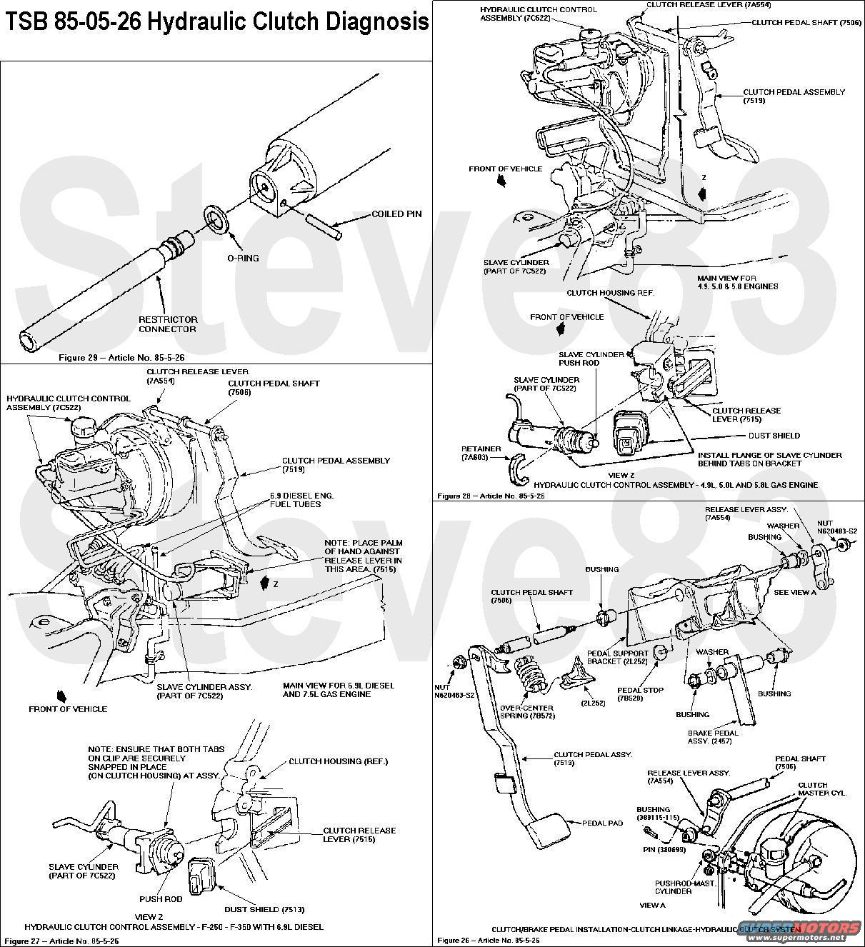
* Hydraulic system component assemblies are now available separately (i.e. master cylinder line with fittings, slave cylinder) so that only the non-functioning component will require replacement when servicing the system. See Figures 28 and 29 for line attachment.
SYSTEM PERFORMANCE
Two basic malfunctions of the hydraulic system may occur and are similar to mechanical system concerns:
1. The release lever is not allowed to return to the free position causing the clutch to slip (similar to over-adjusted mechanical linkage).
2. The release lever is not stroked an adequate distance to fully release the clutch (similar to excessive freeplay with mechanical linkage).
DIAGNOSIS FOR SLIPPING CLUTCH
The clutch master cylinder assembly incorporates a "bleed" port between the cylinder and reservoir which is uncovered when the piston is in the non-depressed position (similar to the brake master cylinder). If the pushrod prevents the piston from fully returning with the pedal not depressed, the system retains hydraulic pressure holding the clutch partially disengaged.
Diagnosis: Push the clutch release lever toward the slave cylinder using the palm of the hand (See Figure 27). If the release lever and slave cylinder pushrod move, the hydraulic system is not causing the clutch slippage and clutch diagnosis should continue.
Clutch Pedal Linkage Adjustment
1983 MODELS - USE OF ADJUSTABLE SERVICE PUSHROD
1. Remove the cotter pin (380699-S) from the clutch lever (7A554).
2. Remove the existing 7641 pushrod from the clutch master cylinder.
3. Replace the pushrod with an adjustable pushrod.
4. Adjust the pushrod as follows:
a. Adjust the pushrod until freeplay between the pushrod and master cylinder cylinder piston is just eliminated.
b. Back off one-half turn.
c. Tighten the jam nut.
d. Assure that the bleed port for self-adjustment located in master cylinder is uncovered. With the slave cylinder mounted, push the clutch release lever (7515) toward the slave cylinder with the palm of the hand.
e. If the lever can be moved, then the bleed port is uncovered and the rod adjustment is correct.
f. If the release lever cannot be depressed, shorten the master cylinder pushrod until the release lever can be moved.
1984/85 MODELS - ADJUSTMENT OF CLUTCH RELEASE LEVER
1. Disconnect the cotter pin, the master cylinder pushrod, and the bushing clutch lever.
2. Disconnect the clutch lever (7A554)from the pedal shaft on the clutch pedal assembly by removing the attaching nut and prying the clutch lever off.
3. Check for evidence of a tight fit between the lever (7A554) and the shaft (7506).
a. If the fit between the lever and the shaft did not create clearly defined spline cuts in the lever, then replace the shaft (7506).
b. If the fit between the shaft and the lever created clearly defined spline cuts in the lever, do not replace the shaft (7506), since the lever may not hold the position.
4. Discard the clutch lever (7A554) (the spline pattern in the hole of the discarded clutch lever will not allow re-positioning on the pedal assembly shaft). If the shaft is to be replaced, remove the pedal overcenter spring (7B572). Remove the nut attaching the clutch pedal assembly to the pedal shaft and remove pedal from shaft. Remove the pedal shaft (7506) from the pedal support (2L252). Discard the pedal shaft (7506).
5. Attach a new clutch lever (7A554) to the master cylinder pushrod with the bushing and the cotter pin.
6. Place the clutch pedal (7519) up against the upper stop on the brake and clutch pedal support bracket (2L252) and allow the overcenter spring to hold it in place.
7. Attach the new clutch lever (7A554) to the shaft of the clutch pedal assembly with nut N620483-S2, making sure that the clutch lever (7A554) is not pushing or pulling the master cylinder pushrod. Torque the nut to 40 to 50 ft.-lbs. Check the clutch system for proper operation.
DIAGNOSIS FOR INADEQUATE CLUTCH RELEASE (HARD SHIFTING/GEAR GRINDING)
Diagnostic Procedure
Check the rod motion of the clutch housing mounted slave cylinder. With the clutch pedal pushed through its full travel, the slave cylinder pushrod should move the minimum distance specified below, against the clutch release lever (7515) head. (Hydraulic slave cylinder must be installed on clutch housing and actuated against the release lever head for this test or breakage of the slave cylinder may occur since the internal spring will fully extend the piston before the pedal is stroked.
Application Minimum Slave Cylinder Rod Motion
6.9L Diesel & 7.5L Gas Engines 13.5mm (17/32")
4.9L, 5.0L & 5.8L Gas Engines 17.5mm (11/16")
1. If the slave cylinder rod moves at least the minimum distance, then the hydraulic system and the in-cab mechanical components are functioning properly. Continue to trouble-shoot for clutch disengagement problems due to the clutch pressure plate, clutch disc, release bearing or the release lever. See Section 16-01 through 16-04 of the 1983-1985 Service Manuals.
2. If the slave cylinder rod does not move at least the minimum distance, then the hydraulic system or the in-cab mechanical components are malfunctioning.
Possible Sources for Inadequate Slave Travel
* Air in the hydraulic system.
* A leak in the hydraulic system.
* The hydraulic system is not being stroked enough by the in-cab mechanical components.
AIR IN THE SYSTEM - BLEED PROCEDURE (All Hydraulic Clutch Systems)
The following procedure is used with the hydraulic system installed on the vehicle. The filling of fluid is carried primarily by gravity.
1. Clean dirt and grease from the cap of the clutch master cylinder.
2. Remove the clutch master cylinder cap and diaphragm and fill the reservoir to the top with approved brake fluid only. (Brake fluid must be certified to DOT 3 specification).
3. Loosen the bleed screw located in the slave cylinder body next to the inlet connection. Collect fluid in a suitable container.
4. Fluid will now begin to move from the master cylinder down the red tube to the slave cylinder.
NOTE: THE RESERVOIR MUST BE KEPT FULL AT ALL TIMES TO ENSURE NO ADDITIONAL INTRODUCTION OF AIR INTO THE SYSTEM.
5. At this point, bubbles will appear at the bleed screw outlet. This means that air is being expelled. When the slave cylinder is full, a steady stream of fluid will come from the slave outlet. Tighten the bleed screw.
6. Assemble the diaphragm and cap to the reservoir, the fluid in the reservoir should be level with step.
7. Exert a light load (approximately 30 lbs.) to the slave cylinder piston by pushing the release lever towards the front of vehicle. Loosen the bleed screw while maintaining a constant light load. Fluid and any air that is left will be expelled through the bleed port. Tighten the bleed screw when a steady flow of fluid is visible and no air is being expelled.
IMPORTANT: Tighten the bleed screw before releasing the load on the release lever or air will be sucked into the system.
8. Add fluid level in reservoir to level at step. Assemble the diaphragm and cap. If necessary, repeat steps 7 and 8 if evidence of air still exits.
9. Exert a light load to release lever as in Step 7, but do not open the bleed screw. The piston in the slave cylinder will move slowly and firmly down bore. Check for air in the red tube. If air is present, force it into the master cylinder by tapping on the tube. Release the load slowly. Repeat 2-3 times.
10. From above actuate the clutch pedal slowly and check for air in the red tube. If air is present, repeat Step 9; fluid movement will force air into reservoir. Repeat 2-3 times.
11. The hydraulic system is now fully bled and should release the clutch. Check vehicle by starting, pushing clutch pedal to the floor and selecting reverse gear. There should be no grating of gears; if there is and the hydraulic system still contains air, repeat the procedure from Step 7.
IN CAB MECHANICAL COMPONENT DIAGNOSIS
1. Installation of correct clutch pedal (1984 Model only) - check that the vehicle is equipped with the proper clutch pedal. Vehicles with the 4.9L, 5.0L or 5.8L engine use pedal part number E4TA-7519-AB which has a welded-on stop which hits the floor. The 6.9L Diesel and 7.5L engines use pedal E4TA-7519-EB which does not have a welded-on stop. Replace the pedal if necessary.
2. Clutch Pedal Linkage Adjustment - Disconnect the cotter pin (380699-S) and the master cylinder pushrod from the clutch lever (7A554). Refer to Figure 26.
* (For 1983 only) Push the master cylinder pushrod forward until it is seated in the pushrod pocket in the master cylinder and check the alignment of the hole in the pushrod with the stud on the clutch lever (7A554).
* If the pushrod hole misaligns from the clutch lever stud by more than 1/8 inch in 1983 vehicles or by more than 1/16 inch in 1984 and 1985 vehicles, then the in-cab linkage is mispositioned. Adjust the pedal linkage per Section C-2 (clutch slipping).
3. Clutch Pedal Stroke Restriction - If the pushrod aligns with the clutch lever stud, then the clutch pedal travel is being inhibited by component other than clutch in-cab linkage. Re-attach the master cylinder pushrod to the clutch lever. Check the clutch pedal travel with a tape measure. Measure the distance between a chosen spot on the front edge of the seat and the pedal. Measure for two conditions: pedal fully up and pedal fully down. The difference between these two measurements equals the pedal travel. Minimum acceptable travel is shown below:
Application Minimum Pedal Travel
1983 6.9L Diesel & 7.5L Gas Engine 6-1/8"
1985 6.9L Diesel & 7.5L Gas Engine 5-3/4"
1984/85 4.9L, 5.0L, & 5.8L Gas Engines 5-3/4"
A possible source of restricted stroke is excessive under carpet padding or "bunching up" of the carpet or padding.
Master Cylinder Assy. (7A543)
PART NUMBER PART NAME
E3TZ-A '83 6.9/7.5L F-Series & All 84/85 F-Series
E4UZ-A 84/85 Econoline
E3TZ-B All Ranger & Bronco II
Slave Cylinder Assy. (7A564)
PART NUMBER PART NAME
E4TZ-A 84/85 F, B, E with 4.9/5.0/5.8L
E3TZ-A 83-85 6.9/7.5L F Series
E3TZ-B 83/84 2.2L Diesel Ranger
E3TZ-C 83/84 2.8L Ranger/Bronco II
E3TZ-D 83/84 2.0/2.3L Ranger
Master Cylinder to Slave Tube Assembly (7A512)
PART NUMBER PART NAME
E3TZ-A '83 6.9/7.5L F-Series & All 84/85 F-Series
E4UZ-A 84/85 Econoline
E3TZ-B 83/84 2.0/2.3L Ranger
E3TZ-C 83/84 2.2L Diesel Ranger
E3TZ-D 83/84 2.8L Ranger/Bronco II
Clutch Fluid Reservoir Assy. (7K500)
PART NUMBER PART NAME
E3TZ-A All Ranger & 84/85 Econoline
Master Cylinder Pushrod Assy. (Adjustable) (7641)
PART NUMBER PART NAME
E3TZ-B 1983 6.9/7.5L F-Series
Kit Pin & O-Ring (7560)
PART NUMBER PART NAME
E2TZ-A All (line to cylinder) for service of damaged pins and O-rings
NOTE: 1985 RANGER UTILIZES A CONCENTRIC SLAVE CYLINDER.
OTHER APPLICABLE ARTICLES: None
WARRANTY STATUS: INFORMATION ONLY
For other TSBs, check
here.
--------------------------------------------------------------------------------
TSB 90-16-7 Clutch Cracks Firewall
Publication Date: AUGUST 1, 1990
LIGHT TRUCK: 1984-90 BRONCO, F-150, F-250, F-350
1988-90 F SUPER DUTY
ISSUE: Incomplete clutch release and/or hydraulic fluid leaking into the cab from the clutch master cylinder may be caused by the reinforcement plate on the clutch master cylinder separating from the dash panel. The separation of the reinforcement plate reduces the clutch master cylinder pushrod travel. Reinforcement plate separation can also cause deflection of the clutch master cylinder that results in a misalignment of the pushrod to the clutch master cylinder. Misalignment causes the "O" ring in front of the secondary seal to leak hydraulic fluid.
ACTION: Inspect the truck and, if necessary, use the following service procedure to install a reinforcement kit.
***I MAY ADD THIS LATER - IT'S VERY LONG*** Look it up here:
http://www.revbase.com/BBBMotor/--------------------------------------------------------------------------------
TSB 85-05-24 Correction
TSB 85-01-20 Clutch Slow in Cold Weather
Dow 470 brake fluid is marketed under NAPA label/number 45012 (12 oz. container).
WARRANTY STATUS: INFORMATION ONLY
--------------------------------------------------------------------------------
See also:

.

.

.