|
|
These are OK, but I want to be able to adjust them from inside, and not have to reset them if I fold them off-roading.
|
|
|
Hi-Lo Western Breakaway Side Mirror 1 Outside Rear View Mirror Gasket (Upper) 17724 2 Screw(s) N806345-S47 (T30 M6x1.00x20mm) 3 Riv-Nuts N803763-S36 4 Outside Rear View Mirror Gasket (Lower) 17724 5 Outside Rear View Mirror 17682 6 Outside Rear View Mirror Head 17723 A Tighten to 4-12 N-m (35-106 Lb-In) Aftermarket copies use a common hex-head bolt to attach the mirror post to the arm; OE uses this countersunk bolt. The OE mirror head is a convoluted plastic form with a stainless skin glued on; aftermarket is a hollow stainless shell, which is why they vibrate much more than OE. See also:  .  . 
|
|
|
 MirHiLoNutserts.JPG | Hits: 1495 | Size: 84.1 KB | Posted on: 1/22/13 | Link to this image MirHiLoNutserts.JPG | Hits: 1495 | Size: 84.1 KB | Posted on: 1/22/13 | Link to this image
Doors built with Hi-Low-Mount breakaway mirrors have a bonded reinforcement around the nutserts (rivnuts) for the lower mount.
|
|
|
OE Bubble-Back Mirror Construction
Aftermarket copies use the stainless shell as the mirror head's structure, which is why they vibrate so badly. The only problem with the OE mirror is that the glue separates. I don't know why no one simply re-glues the shell on - this one has the remains of duct tape all over it. A few drops of E6000 would have lasted another 20 years, and no one would have know there had ever been a problem.
|
|
|
I drilled out the spot welds to remove the nut plate, but I reused it later.
Screws are T30 button head M6x1.00x20mm.
|
|
|
The rear screw hole is exactly 18 3/4" from the front edge of the door, so mark a vertical line coming up from the body line.
|
|
|
Align the bottom edge of the new mirror's gasket (which must be removed from the mirror) with the body line, and center the original 18 3/4" mark in the rear hole. Then mark the centers for the front & rear holes.
|
|
|
With the gasket held by the rear screw and the original nut plate, set a hole saw over the support arm hole so it totally covers it, but doesn't hang over the gasket, then mark & punch the center. I think this is a 1 1/2" hole saw, but I'm not sure.
|
|
|
Then swing the gasket out of the way and cut the support arm hole.
Note that I drilled the spot welds for the original nut plate first and removed it.
|
|
|
Reinstall the gasket on the mirror and feed the wiring harness & support arm through the hole. The original nut plate can be cut so the nuts can be reused, but the screws are different. I had to improvise temporarily.
|
|
|
Because of the large washer, you can drill a large (~3/8") hole and set the arm where it needs to be.
|
|
|
The bolt fell exactly 2 1/2" above the power window switch hole in the inner skin, but it's OK to drill a slightly oversized hole. The washer will still catch and it allows you to adjust.
|
|
|
I just put the old screws back into the lower holes until I decide what to do with them. The new screws are T25 oval head M6x1.00x25mm.
UPDATE: Eventually I found the perfect way to get rid of those holes & screws: smash the door against a tree, then replace it with a door built for these mirrors! 
|
|
|
This is how it looks. Since I had already converted my door panels to this style, I also already had the wiring for the power mirrors.
|
|
|
It took about 2 hours from the time I pulled the other mirror, but I was learning.
|
|
|
With what I learned, the second side only took ~45min.
|
|
|
But since I started late, I left the driver's side until the next day.
|
|
|
You have to look REALLY close and know what to look for to know from this angle that this ISN'T a stock '92-96 door.
|
|
|
I still haven't decided what to do about the lower holes - maybe I'll use a turn signal (like some new car/SUTs have) to hide them.
UPDATE: ...or maybe I'll bash the door into something, and replace it with a newer skin that doesn't have those holes.
|
|
|
Until today, every shiny mirror front I had seen was chromed plastic. But after removing this dented one & finding no dents on the back, I looked a little closer & saw the swaged edge of the polished stainless steel face. I used small end-cutting pliers to fold the edge back, & remove the plastic backing. I washed the plastic, and sprayed it with some satin black, and then baked it in front of a 300W halogen light for a few minutes.
Apparently, the stainless face was only used on VERY early '92 mirrors because I've found '93 & '96 mirrors with the plastic face.
|
|
|
This one is chromed plastic, so the only way to black it out is to wash, scuff, & paint it. I'm using Dawn dish soap, a 100-grit pad on an orbital sander, and Krylon Fusion Satin Black.
|
|
|
 PowerMirrors96Bronco.JPG | Hits: 7231 | Size: 51.47 KB | Posted on: 9/5/07 | Link to this image PowerMirrors96Bronco.JPG | Hits: 7231 | Size: 51.47 KB | Posted on: 9/5/07 | Link to this image
Wiring Diagram for '96 Bronco Mirrors ERROR: circuits 540 & 543 should indicate 12V (L), 0V (R)  .  Signal mirrors display a supplemental turn signal through the outside rearview mirror glass surface. The signal is directed toward vehicles in adjacent traffic lanes and is not visible to the driver of the equipped vehicle. The signal mirrors are equipped with an integrated light sensor and automatically adjust the brightness of the signal display for day and night operation. The signal is connected directly to the turn signal wiring. WPT-382 (natural) shown; WPT-311 (natural) or WPT-174/712 (black) mate Non-signal mirrors are similar, but with a 4-position connector using 3 pins.
|
|
|
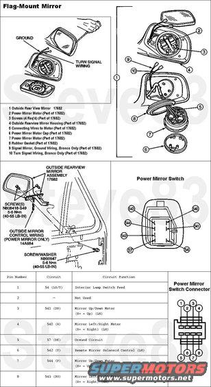 MirrorFlagMount.JPG | Hits: 5566 | Size: 51.33 KB | Posted on: 10/24/07 | Link to this image MirrorFlagMount.JPG | Hits: 5566 | Size: 51.33 KB | Posted on: 10/24/07 | Link to this image
Mirror, Outside Flag-Mount IF THE IMAGE IS TOO SMALL, click it. F7TZ17682DAA Right chrome manual F7TZ17683DAB Left chrome manual F1TZ17682C Right black manual F1TZ17682D Left black manual F7TZ17682BAA Right chrome power F5TZ17683BA Left chrome power F5TZ17682E Right black power F5TZ17683E Left black power Mirror Glass Removal: 1. Push in on the inboard edge of the glass assembly until it stops. 2. Protect mirror body with a rag or similar material at the outboard edge and insert a flat blade screwdriver (in about one inch) between the mirror body and glass assembly. 3. **THIS DOESN'T WORK** Pry the glass assembly out from mirror body until it snaps loose. **THE GLASS INVARIABLY SNAPS BEFORE THE TABS RELEASE**  4. Remove screwdriver and continue to pull the glass assembly by hand until it is completely unsnapped. 5. ('96 Bronco only) Scribe the wire colors into the plastic for reassembly later, then disconnect the two circuits (turn signal and ground) from the terminals on the back of the glass assembly. Mirror Front Trim Removal: 1. Remove the 4 T-10 screws from the outer corners behind the mirror glass. 2. Lift the trim away from the mirror head. Mirror Motor Removal: 1. Mark the motor with tape/grease pencil/scribe to indicate top of motor. 2. Remove the four screws attaching the motor to the mirror body. 3. Pull motor away from the mirror body. 4. Remove the plastic cover plate from the back of the motor. Pull off by hand. 5. Use masking tape on the wires. Mark on the wire its location in the motor with the terminal number shown on the motor where the wires plug in, and scribe the wire colors into the plastic. 6. Carefully pull the wires/terminals out of the motor. Mirror Assembly Removal: 1. Remove front door trim panel (23942). 2. On power mirrors, disconnect outside mirror control wiring (14A684) at inner door skin below speaker. 3. Remove two black countersunk T-25 screws attaching outside rear view mirror (17682) to the exterior of the front door (20124). 4. Remove one 8mm screw attaching outside rear view mirror to the interior of the front door. 5. Remove outside rear view mirror. Mirror Head Removal: 1. Remove T-10 screw from mirror base gasket, and slide gasket off base brace arm & wiring (if equipped). 2. Remove two T-20 screws from base and lift mirror head away from base, feeding power mirror wiring (if equipped) through pivot rivet. Mirror Head Installation: Follow removal procedures in reverse order. Mirror Motor Installation: 1. Install wires into the motor by matching the terminal number marked on the wires and on the motor. Remove masking tape from the wires. 2. Make sure wires are placed in the retaining slots in back of motor, then align the opening in the plastic cover plate with the wires on the back of motor and push on back cover. 3. Make sure the rubber seal is properly installed on the motor. 4. Position motor in mirror body using the mark (added during removal) indicating top of motor and line up the four screw holes. 5. Install the four screws and hand-tighten. Do not overtighten. Mirror Front Trim Installation: Follow removal procedures in reverse order. Mirror Glass Installation: 1. ('96 Bronco only) Connect signal and ground wires to mirror glass. Verify signal display operation by operating the right and left turn signals. 2. Position glass assembly in mirror, making sure the U-shaped alignment tabs on the glass assembly are lined up with the motor actuator bar, and move glass around slightly until it drops into place. 3. Push on center of the glass assembly to snap it into place. 4. Check glass assembly for looseness. If loose, push on glass assembly until it is fully seated. Mirror Assembly Installation: Follow removal procedures in reverse order. Mirror Control Removal: 1. Insert a small, thin-bladed screwdriver into spring tab slots located at front and rear of window regulator switch housing (14527) and apply pressure to make the window regulator switch housing pop out. 2. Remove three screws attaching connectors to window regulator switch housing. 3. Remove outside rear view mirror control (17B676) by carefully prying the outside rear view mirror control from connector using a small screwdriver, then prying mirror control from window regulator switch housing. Mirror Control Installation: Follow removal procedure in reverse order. The outside rear view mirror control is keyed to the connector and can be installed only one way. See also:  . 
|
|
|
I also learned that the internal wiring of these switches is different, so the stock wiring harness requires that type AA (F2TZ-17B676-A) be used. It would be REALLY easy to rearrange the pins in the wiring connector, and I'll probably do that eventually since the AB switch is easier to find.  Some Ford wiring diagrams suggest that AB has internal illumination, but I haven't confirmed that.
|
|
|
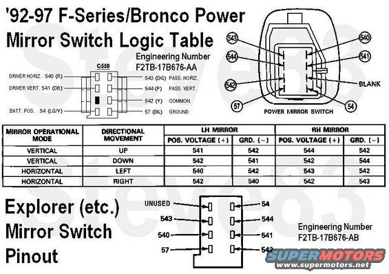 PowerMirrorSwitchLogic.JPG | Hits: 1733 | Size: 123.28 KB | Posted on: 10/18/13 | Link to this image PowerMirrorSwitchLogic.JPG | Hits: 1733 | Size: 123.28 KB | Posted on: 10/18/13 | Link to this image
Mirror Switch Logic Table & Pinouts To use an Explorer switch in a Bronco/F, simply move the wires in the connector to match the switch you want to install. See also: 
|
|
|
Damaged '96 Bronco Turn Signal Mirrors
Even broken, these are VERY desirable & valuable, so I'll repair them using parts from common (non-turn-signal) mirrors. Only the plates with the LEDs and the wiring harnesses are unique to '96 Broncos - the first US production vehicle with turn signals on the side mirrors. The rest of the mirror parts are common to '92-96 Ford trucks.
The light sensor causes the signal to be dimmer at night & brighter in day, or when headlights strike the mirror. The lens prevents the driver from seeing the LEDs.
Under normal daylight, the LED arrays each draw 4.3mA @ 14VDC.
|
|
|
Flag-mount Mirror Repair Start with any donor mirror of the same side and with the good parts that are broken on the desirable mirror. The broken one here is a rare '96 Bronco power signal mirror, and the donor is a common (cheap) manual mirror with a black front trim. Both mirrors must be dismounted before any inside parts can be swapped, but it might be easier to remove the mirror glass while the mirror assembly is still attached to a door since that's the best way to hold it. This one was already broken, so it didn't matter. Note the 8-position (5-wire) connector on the upper mirror, indicating it's a '96 Bronco signal mirror. All other power mirrors have a much smaller 4-pin (3-wire) connector. 
|
|
|
The mirror head always cracks here since the REAR shell is what's attached to the pivot tube, and the front shell is only attached at a couple of sonic weld points.
 .  . 
|
|
|
Remove the T-10 stainless screw that retains the mirror gasket.
|
|
|
Tuck the wiring harness under the arm and slide the gasket off.
|
|
|
Remove the 2 T-25 screws from the bottom of the mirror base. The outer screw is accessible while the mirror is installed on the truck, but removing it before this step is pointless.
|
|
|
Remove the head from the base, working the wiring (if equipped) through the base. The connector doesn't fit through - the wires must either be disconnected from the motors or depinned from the connector, & then pulled out thru the base.
|
|
|
The pivot tube & square pressure plate. Note that the front shell is barely attached (if at all). So all the force is concentrated on the rear shell, causing it to crack.
 . 
|
|
|
Pivot plate & motor gasket differences; the later design (~'94-96) is on the L.
There was also a change to the mirrors' shiny front panel in late '92. Early fronts were polished stainless swaged over a black plastic backer; all later ones are chromed plastic.
|
|
|
The pivot tube is swaged together after installing the stack on the mirror head. When the head turns, it applies side force to the balls, and some corner force to the top plate. The 3 spring washers above the plate hold pressure on the balls, and the one below holds the plastic mirror head against the black steel plate. 
|
|
|
The pivot tube is swaged together after installing the stack on the mirror head. When the head turns, it applies side force to the balls, and some corner force to the top plate. The 3 spring washers above the plate hold pressure on the balls, and the one below holds the plastic mirror head against the black steel plate. 
|
|
|
Being VERY careful not to crack the mirror glass (assuming it's still useable), tilt the mirror fully DOWN and INBOARD, and pry the outboard upper corner out of the head. Ford says to just pry until the mirror backing plate pops off the tilt ring, but I've never had one come off without shattering the mirror, so I always use picks to release the tabs. Working in good light, peek thru the gap between the mirror plate lip & the head housing. Use picks to gently release each tab by pulling it away from the central ring just a fraction. Sometimes, simply inserting the tip of the pick is enough.
|
|
|
When enough tabs are released, the mirror plate will start to come away from the tilt ring. It may be necessary to swivel the tilt ring to finish removing the mirror, but use a tool to push the ring through the gap. Pushing on the mirror will re-lock the tabs. For power mirrors, you can also use the motors to drive the tilt ring around for access to other tabs.
If equipped, disconnect the signal wires, noting their positons. Although the terminals are identical, the signal LEDs won't work if the wires are reversed.
|
|
|
Driver signal mirror LED wiring colors. If the wires are reversed, the LEDs won't work. Scratch the colors into the plate before disconnecting the wires.
|
|
|
Passenger signal mirror LED wiring colors. If the wires are reversed, the LEDs won't work. Scratch the colors into the plate before disconnecting the wires.
|
|
|
This mirror back was molded in 1/96, and the mirror head in 10/96 - quite a spread, considering Ford's manufacturing practices.
|
|
|
This mirror back was molded in 9/95, and the mirror head in 12/96 - quite a spread, considering Ford's manufacturing practices. But maybe Muth (the mirror mfr. & supplier) did things differently.
|
|
|
This mirror wasn't replaced correctly (it's aftermarket glass, so it doesn't fit down into the factory backing plate), and since I can't see the LEDs thru it, I'll remove it & see what's up.
|
|
|
The reason this glass wasn't installed fully is that it doesn't fit into the backing plate's lip. Apparently, it's aftermarket glass.
This mirror's LEDs draw 4.3mA @ 14VDC.
|
|
|
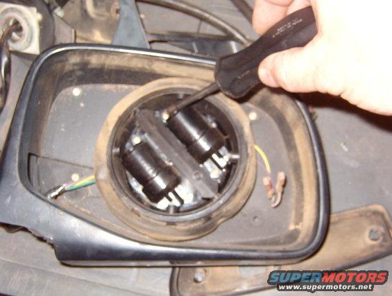 08MotorScrews.JPG | Hits: 2165 | Size: 54.22 KB | Posted on: 10/24/07 | Link to this image 08MotorScrews.JPG | Hits: 2165 | Size: 54.22 KB | Posted on: 10/24/07 | Link to this image
Mark TOP and the side on the tilt ring assembly first - it's very difficult to figure out later. Remove the 4 T-10 screws that hold the ring in the mirror head.
If necessary, the 4 T-10 screws around the tilt ring can be removed to release the mirror's front trim for cleaning, or to remove the shiny metal front & make it black.

|
|
|
Note the wire routing for proper reassembly.
|
|
|
Passenger signal mirror wire colors. Remove the motor cap (on the bottom), and scratch the wire colors into the motor housing for proper reassembly. Also, mark TOP and L or R on the motor assembly. The wires pull straight out of their terminals. If it's intact & not holding dirt/water, the boot can stay on.
|
|
|
Driver's signal mirror wire colors. The top terminal (Pu) is #4.
|
|
|
Draw the wiring out through the pivot tube.
|
|
|
The donor mirror is disassembled similarly. After disassembly, all the parts can be cleaned & the visible black plastic painted (or not).
|
|
|
If necessary, remove the donor head from its base to install the wiring.
|
|
|
For power mirrors, install the boot onto the motors as shown. Then insert the wires and install the cap with the wires in the guides. If the boot is damaged, install the rip or hole at the bottom so water can drain.
|
|
|
If either drive rack is damaged, it can be easily popped out of its socket on the tilt ring & replaced with a donor part.
The "T" scratched into the motor housings indicates "TOP".
|
|
|
Since the non-signal backing plate is common & useless without glass, there's no point trying to save it. This cutting wheel gently removes the plastic without stressing the glass. Since the silvering is on the other (viewing) side of the glass, small nicks on this side won't affect it.
After a few seconds, I was covered in black powder, so I finished the job in front of a squirrel cage blower.
|
|
|
The silicone is so strong (even at this age) that it's hard to separate the plate without destroying the glass. And after cutting all this away, I discovered there's also some double-sided foam tape in the middle. The driver's glass doesn't use tape - only silicone.
Later, I figured out a better way, that doesn't hurt the plate, either.
|
|
|
After grinding away the backing plate on each point of attachment, the glass comes away intact.
|
|
|
A non-signal driver's mirror has 6 silicone spots.
|
|
|
Use a razor to remove all residue. Originally, I tried to scrape it while holding the glass by hand, and (no, I didn't cut myself) I let the scraper slide over the edge, and it chipped the glass in the lower L of the pic.
|
|
|
All mirror glass for these trucks is half-silvered, so it all works with signal mirrors. But some aftermarket glass isn't exactly the same size/shape, so it may not fit on the original backing plate. Ford glass does.
|
|
|
I used E6000 to glue the glass to the backing plate, instead of silicone sealant & foam tape, like the factory.
|
|
|
To make future removal less-risky, I broke off about half the tabs on the mirror plate. It would be wiser to grind off some of the teeth on the tilt ring (since that's a more-common part and so, easier to replace), but a couple of these were already cracked.
|
|
|
Install the motors (or tilt ring) into the head, install the head onto the base, and connect the signal wiring (if equipped). Test signal & motor operation, noting polarity of signal wires. After ensuring proper operation, align the mirror over the tilt ring & snap it down by pressing directly over the ring until all tabs snap over the tilt ring's teeth.
|
|
|
Rare '96 Bronco Signal Mirror I've called Muth (the orignal manufacturer & supplier) and they don't acknowledge the existence of these mirrors, so there are no replacements available anywhere but the junkyards.  Fortunately, I've found a way to mimic them, using modern parts that ARE still available. Keep reading the NEXT several pages...
|
|
|
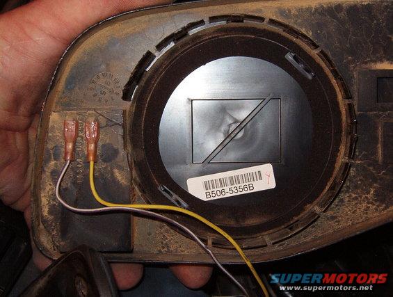 15SignalWires.JPG | Hits: 1888 | Size: 64.53 KB | Posted on: 10/24/07 | Link to this image 15SignalWires.JPG | Hits: 1888 | Size: 64.53 KB | Posted on: 10/24/07 | Link to this image
The signal wires must be connected properly since the LEDs require correct polarity to function. Test the signal & motors before installing the mirror onto the tilt ring since it's VERY difficult to remove intact.
Signal mirrors display a supplemental turn signal through the outside rearview mirror glass surface. The signal is directed toward vehicles in adjacent traffic lanes and is not visible to the driver of the equipped vehicle.
The signal mirrors are equipped with an integrated light sensor and automatically adjust the brightness of the signal display for day and night operation. The signal is connected directly to the turn signal wiring.
|
|
|
Without the glass, the LEDs are visible from a much wider angle. But this one's top row isn't working. Above the array, the photosensor is visible on the PC board.
The rectangular holes in the other side of the backing plate appear to be for a heating element which was never offered by Ford or Muth. But I've found a way to add heaters to them. Keep reading the NEXT several pages...
|
|
|
'92-96 Power Mirror Circuit 
|
|
|
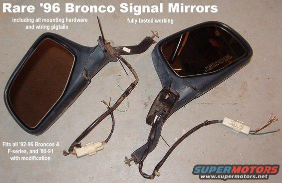 SignalMirrorPair.JPG | Hits: 3033 | Size: 48.41 KB | Posted on: 10/25/07 | Link to this image SignalMirrorPair.JPG | Hits: 3033 | Size: 48.41 KB | Posted on: 10/25/07 | Link to this image
SOLD Rare '96 Bronco Signal Mirrors The only differences between these & normal mirrors are: 1) the mirror backing plate (NOT the glass) which includes the directional LEDs & a light sensor 2) the wiring which incudes 2 extra wires and uses a 6-position connector Thoroughly tested working. Includes all mounting hardware & pigtail connectors for wiring into any vehicle. Mirrors are direct-replacements for all '92-97 Ford truck flag-mount mirrors, and can be easily retrofitted to any '80-96 ('97 over 8500 GVWR) fullsize Ford truck or Bronco. Ships as 10 lbs 19x13x12". Fasteners are: 8mm (5/16") bolt for arm to inner door skin two T25 for outer door skin 
|
|
|
SOLD Driver's Mirror '92-96, power flag-mount with chrome front
Note the common 4-position (3-wire) round connector used on most '92-97 trucks. Only some '96 Broncos got the larger 8-position (5-wire) signal mirrors.
|
|
|
SOLD Chrome Power Mirror for '92-96 ('97 over 8500 GVWR) fullsize Ford truck or Bronco. Tested working. Includes all mounting hardware.
Note the common 4-position (3-wire) round connector used on most '92-97 trucks. Only some '96 Broncos got the larger 8-position (5-wire) signal mirrors.
|
|
|
Since factory signal mirrors are so hard-to-find, building them is another option. These LED chevrons were made by Shark Racing (back in 2012, now from many eBay sellers), and are specifically built for this purpose. They recommend mounting them between the backing plate & the glass. But because it's nearly impossible to separate the mirror from the plate without destroying either of them, and because putting them there doesn't make them directional, I'm putting them on the backs of the plates. First, I powered one and created a paper template by silhouette. READ THE NEXT CAPTION...
|
|
|
After scanning & cleaning up the template, I printed a few, cut them out, trimmed the tip to offset it, then drilled through the plastic and cleaned out the burrs. I also had to remove one of the plate's mounting tabs where the top of the chevron overhangs. Later, I also trimmed that corner of the chevron.
READ THE NEXT CAPTION...
|
|
|
Since the paper template was offset outboard, each hole is slightly outboard of its LED, making the LED only visible when viewed from the outboard side. This is a really easy way to achieve the same effect that Muth & Ford needed a special prismatic lens for.
READ THE NEXT CAPTION...
|
|
|
With the mirror glass installed over the offset holes, very little of the LED light is apparent to the vehicle occupants; mainly just around the edges of the glass. The pattern on the wall shows how directional it is.
READ THE NEXT CAPTION...
|
|
|
I don't want to have to destroy the chevron or the plate to separate them, so since there's virtually no load pushing them apart, I only used a few drops of glue to hold it on. And I only applied the glue after the chevron was in-place so it will be easy to cut away later. There's no glue between the chevron & the plate.
When I actually connect the wires, I may desolder these wires from the chevrons & solder terminals on, like the factory mirrors have, so the mirror plates will be easier to remove from the mirror heads.
|
|
|
This heating pad fits pretty well in the swivel cup on the mirror backing plate, and after testing it in my deep freezer, it works well enough for me. Obviously, they don't heat the WHOLE mirror, but it's enough to make them useable. Fortunately, I added wiring for mirror heaters to the door harnesses last year when I had them out, so connecting them will be easy. And like the LEDs, breaking the glass won't hurt the heating pads. I'm using 3M Super77 spray adhesive on the pads to attach them to the plates.
Wiring these is relatively easy in Broncos since most of them already have a rear defrost timer in the dash. But it's not much harder in trucks without that, and a timer isn't really necessary. These can run continuously without damaging themselves or the mirrors, so a simple switch is good enough (I recommend one with a pilot light). And they draw very little current, so it's safe to add them to an ignition-switched circuit so they go off with the key.
UPDATE 3/15/15:
I built & installed heated signal mirrors for a local Bronco enthusiast last year, and he reported after the recent blizzard that the heaters WORKED.
UPDATE 12/15/21:
I still haven't wired my heaters up, but I ripped a mirror off off-roading today so I may wire up at least that one when I fix it.
KEEP READING THE NEXT PAGE...
|
|
|
OBJECTS IN MIRROR ARE CLEANER THAN THEY APPEAR So that's a heated signal power mirror with puddle lamp & off-road light that fits '80-96 F-series & Broncos.  .  .  .  .  Next time, I'll add memory... Incidentally... A few years after I posted this pic, Ford added the option of off-road lights to new 4WD truck mirrors. But theirs can't be aimed by the occupants like mine can. UPDATE: 2021 (8 years later) they're still working perfectly. KEEP READING THE NEXT PAGE...
|
|
|
Loaded Mirror IF THE IMAGE IS TOO SMALL, click it. This now has almost everything modern mirrors have, plus the off-roading lights (which Ford added to new trucks the year after I did this). 3 wires are still being used for the motors. 2 pins are used for all the grounds (to make sure there's enough ground capacity) 1 wire for the turn signal LEDs 1 wire for the flood LEDs 1 wire for the puddle LED I have not yet attempted to add memory to these mirrors, but I assume it can be done. I've added heat to a few sets, including a local friend's Bronco. 
|
|
|
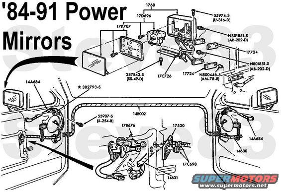 MirrorPwrEarly.JPG | Hits: 1719 | Size: 67.89 KB | Posted on: 11/10/11 | Link to this image MirrorPwrEarly.JPG | Hits: 1719 | Size: 67.89 KB | Posted on: 11/10/11 | Link to this image
|
|
|
2-Position Breakaway Hi-Lo Mount Mirror
The additional arm (barely visible in the diagram below the mirror head) pivots out, shifting the mirror so the driver can see around his own wide trailer.
This rare (pre-'82?) mirror is easily identifiable by the 3-screw-per-pad mounting.

|
|
|
Recreational (Towing) 2-position Side Mirror
1 Outside Rear View Mirror Gasket, Upper 17724
2 Bracket Assembly 17016
3 Outside Rear View Mirror Head 17723
4 Bracket Assembly 17059
5 Screw(s) (4 Req'd) N806345-S47
6 Outside Rear View Mirror Gasket, Lower 17724
7 Rivet-Nut (4 Req'd) N803763-S36
A Tighten to 4-8 N-m (35-71 Lb-In)
See also:

|
|
|
Optional '82-96 Side Mirrors All metal parts are stainless, except the main arm for the bubble-back Hi-Low Mount Breakaways, which is Aluminum. OE bubble-backs can be identified by: 1) the countersunk Torx screw attaching the mirror head to the arm; aftermarket uses an exposed hex-head. 2) the mirror head is black plastic with the glass & stainless shell glued on and the ball stud embedded; aftermarket mirrors attach the ball stud & mirror glass to the hollow stainless shell (which allows the glass to wobble at highway speed). See also:  . 
|
|
|