The handling of the Ford Excursion has been suspect since day one of the 2000 Excursion all the way to present day (2005 models as of this writing). Ride quality and handling is notibly improved with aftermarket shocks, a rear anti-sway bar, and now radius rods. This article discusses in detail the problem with the factory "traction bar" on Excursions, the benefits of a radius rod, and the installation of LANDYOT radius rods.
These radius-rods will not interfere with a previously installed Hellwig brand anti-swaybar. However, the radius-rods will cause a later installation of the Hellwig anti-swaybar to be more difficult, and should be temporarily removed from the leaf springs (unbolt the square U-bolts) during anti-swaybar installation. It is not known if anti-swaybars from other manufacturers will cause any interference.
|
Step 1: Remove rear wheels
|
a.) Start with any rear wheel you'd like.
This article begins with the passenger side rear wheel. Locate the tab on the beauty cap on each wheel.
b.) Remove beauty caps with tire-iron
Remove the tire-iron from the engine compartment of your Excursion (it's mounted right on top of the raditor--careful, it will be hot if you've driven within the past hour). Use the end of the tire-iron (with the rubber casing) to pry off the beauty caps from your wheel.
c.) Remove lug nuts
Use the other end of your tire-iron to loosen all 8 lug nuts (make sure to loosen lug nuts before jacking the wheel up, otherwise you will have no leverage and the wheel will just rotate if you try to loosen the lug nuts with the wheel jacked up in the air). Or alternatively, use an impact wrench.
d.) Jack up rear of vehicle
Jack up vehicle with a hydraulic jack positioned under the pumpkin of the rear end. This will lift the rear of the Excursion evenly.
e.) Place jackstands underneath the axles.
f.) Remove both rear wheels.
|
|
|
Step 3: Cut off OEM traction bars
|
a.) Locate the OEM traction bars:
b.) Cut off traction bar
We found that cutting from the inside of the traction bar towards you works best.
- Excursions 2000-2003, cut off 14-inches of the traction bar
- Excursions 2004-2005, cut off 16-inches of the traction bar
c.) Clean off any imperfections left on the portion of the traction bar that still exist.
d.) Dispose of the cut-off portion of the OEM traction bars!
|
|
|
Step 4: Cut off plastic retainer tips on leaf springs
|
a.) Locate the plastic tip (or tips, depending on model year) extending through the leaf spring in the way of thes pring-clamp weldment.
The following sketches determine which plastic tips need to be removed.
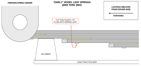
Starting with the 2004 model, the leaf spring lengths are different, and the traction bar rubber snubbers are located in different locations:
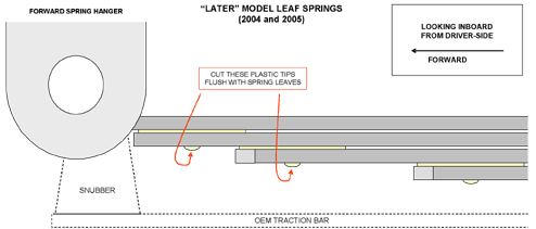
b.) Cut off the plastic tip(s)
A hacksaw blade held in a gloved hand, a wood chisel, or in our case, a grinder can be used to remove these. We highly recommend a grinder for ease and speed.
|
|
|
Step 5: Trim Metal Bump-Stop (Gen-II radius rods ONLY)
|
|
|
|
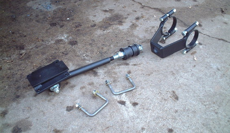
Step 6: Assemble the axle clamp to the rod-arm
|
a.)Remove a 3/4" jam-nut, 3/4" nut, washer, and one of the rubber isolator bushings from the rod-arm
Your kit will arrive with the rod-arm already attached to the spring-clamp. You will need to assemble the axle-clamp to the rod-arm.
b.) Position the axle-clamp on the other bushing as described below
- GEN-I: The box-like structure of the GEN-I axle-clamp should be positioned so the open side of the "box" is facing down.
- GEN-II: The A-frame structure of the GEN-II axle-clamp should be positioned with the cross-brace that ties the "legs" together located on top. NOTE: I did not understand what this meant at the time of install. Simply put, the cross member on the "A-frame" will need to be on the top when this is mounted to the axle. This leaves a nice opening below the rod-arm/a-frame for easy access to the 3/4" nut with a wrench. I didn't follow this instruction and while there is no affect on the performance of the radius rod, it simply makes it a little bit tougher to sneak a wrench in on the nuts when tightening them.
c.) Loosely reinstall these parts, but do not tighten at this time.
|
|
|
Step 7: Position the axle-clamp on the axle housing tube
|
a.) Clean road debris from around the axle housing tube
NOTE: On 2000 through 2003 models, the passenger side installation requires that you disconnect the wire retainer holding the parking brake cable to the right-rear shock abosorber mount. This cable can be tie-wrapped to the radius-rod to limit its movement.

b.) Position the axle-clamp on the axle housing tube
Tip: Use a wood clamp during this process to help secure the radius rod while you install the axle-tube clamps!
- GEN-I: The axle-clamp is to be positioned outboard of the factory leaf spring U-bolts. The open side of the axle-clamps's box-like structure should face downward. Install the clamp-cap, the 1/2" bolts and nuts, but do not tighten at this time.
- GEN-II: Position the A-frame axle-clamp on the axle housing so it straddles the leaf spring U-bolts. Install the clamp-caps, the 1/2" bolts and nuts, but do not tighten at this time. Double-check for a clearance fit with the metal bump-stop by rotating the axle-clamp upward, and make certain there is no interference with the forward end of the upper inboard bolting tube of the axle-clamp, nor with the bolt head.
|
|
|
Step 8: Secure radius rod to leaf spring
|
a.) Position the spacer-plate on top of the leaf springs in line with where the spring-clamp weldment will be positioned beneath the leaf springs.
The "tab" portion of the spacer-plate should point outward.
b.) Install the square U-bolts
10. Slip the square U-bolts from above the leaf springs down over the forward and aft notches of the spacer plate. These square U-bolts shall straddle the leaf spring and the narrow ends of the spacer-plate. Note: If one leaf is not aligned with the others, it can be nudged sideways with a crowbar.
c.) Make sure the radius rod leaf spring mount is orientated as follows
Rotate the entire radius-rod assembly upwards, pivoting about the axle housing, to the square U-bolts hanging from the leaf springs. The hinge shackle plates should be pointed downward, and the 1/4" thick spacer welded to the top surface should be orientated to the forward end of the spring-clamp. NOTE for sway bars: The notch cut into the side of the spring-clamp assembly should be facing inboard, and is provided to clear the vertical drop-link of a Hellwig brand anti-swaybar.
d.) Slide the spring-clamp until it's about 1/8" to 3/16" forward of the next leaf spring as you tighten the U-bolt nuts.
e.) Tighten all the U-bolt nuts evenly (18ft-lbs max. for 3/8" dia. U-bolts, or 25ft-lbs max. for 7/16" dia.).
|
|
|
Step 9: Final tightening
|
NOTE
It is imperative that compressing the rubber isolators on the rod-arms be done equally with the forward and aft nuts in order to avoid any unequal forces between the forward and aft sides of the rear axle, or from one side of the vehicle to the other. Final tightening of all fasteners should be accomplished with the vehicle sitting with its weight distributed among all four tires (suspension loaded). Ensure that you tighten the jam-nuts after finalizing the isolator compression.
a.) 13. Hand-tighten the 3/4" nut on the forward end of the rubber isolators
This will push the axle-clamp against the rear axle, and rotate the axle-clamp structure until it is aligned with the rod-arm (see sketch below). After the axle-clamp is positioned, tighten the 1/2" nuts.
b.) The nuts on both sides of the isolator bushings must be tightened equally. This step is very important.
Loosen the 3/4" nut tightened in the previous step, then hand-tighten both (forward and aft) 3/4" nuts an equal amount until resistance is felt, then wrench-tighten both nuts equally until the washers bottom out against the copper sleeve located inside the rubber isolators bushings. Tighten the 3/4" jam-nuts to lock the nuts in place.
|
|
|
Step 10: Re-install wheels
|
a.) Reinstall the lug nuts on the wheel by tightening in a star-shaped pattern
You will have to have the wheel on the ground before you can fully tighten the lug nuts (otherwise the wheel will spin when jacked up in the air).
b.) Make final tightening with a torque wrench to 165 ft-lbs.
c.) Admire your work and take a test drive!
d.) After 1 week, inspect all bolts to ensure they are still tight.
|
|
|
Conclusion
|
|
The radius rods have greatly improved the driving characteristics of my Excursion. I no longer am doing "white-knuckle" driving and don't need to constantly adjust the steering. It tracks so much straighter on the road at highway speeds now that I've even noticed I don't get fatigued as quickly on long road trips. With much less effort going into keeping the X in a lane on the highway, it makes driving it quite enjoyable again!
|
|
|
Where to buy?
|
|
You can find purchasing information here: link
|
|
|
Additional Questions or Comments?
|
|
Do you have additional questions or comments about this install article? Please discuss them in this forum thread.
HINT: Click the "printable page" button below to view this article in its entirety with higher-resolution photos.
|
|