![TSB 92-01A-09 Guidelines for Modifying Light Truck Drivelines
Publication Date: 01/26/92
IF THE IMAGE IS TOO SMALL, click it.
LIGHT TRUCK: 1989 and after BRONCO, ECONOLINE, F SUPER DUTY, F-150-350 SERIES
ISSUE: Qualified Vehicle Modifier (QVM) Bulletin Number 14 provided guidelines for modifying light truck drivelines to help ensure proper driveline integrity. The bulletin is printed here as an added aid to the service technician.
Improper driveline modifications were found to influence recent service claims for transmission damage, premature wear-out of U-joints, and noise and vibration. When modifying a driveline use the following guidelines to help ensure proper driveline integrity. Although these guidelines cover the most immediate concerns, they are not comprehensive. The reader is encouraged to further consult the references listed at the end of this bulletin.
In general, limit the amount of balance weight to approximately 3 ounces or less at each end of a shaft. Excessive weight required to balance indicates that the shaft is likely to be distorted beyond the runout specifications and should not be used. Compare the runout of the shaft against the following specifications to determine whether a shaft is worth balancing.
A list entitied Things-Gone-Wrong follows. This list contains the things-gone-wrong commonly found on vehicles with modified drivelines. Vehicle modifiers are encouraged to use this list to quickly identify problem areas in their build process.
Balanced shafts on modified vehicles are found to have over 4 times the maximum imbalance allowed by the guideline.
Muffler pipe used to make driveshafts (poor quality pipe - non-uniform metal thickness, oval/not round, rusts easily)
^ Too many balance weights used to balance a shaft
^ Driveshafts, made longer, are not increased in size when required.
^ U-joints not often up-sized, or up-graded, when required
^ Rear axle pinion angles too large on substituted or modified rear suspensions
^ Excessive U-joint angles on modified wheelbase/frame-stretched vehicles
^ U-joints not in line (in phase) at either end of a modified driveshaft. The yoke ends are crooked when welded onto the tube.
^ Alignment arrows on slip yokes and tube shafts not aligned. Sometimes the slip yoke is found turned by one spline tooth when installed, resulting in the driveline being several degrees out-of-phase.
^ Improper electrical grounding of eddy-current type brake retarders
Poor driveline modifications have been occurring for many years. These modifications often set up powerful vibration resonances in the driveline that pound and bend the critical links surrounding the shafts - joints, transmissions and axles. Frequent joint replacements, cracked manual transmission housings, and needless front wheel alignments and balances, are often attributable to poor driveline modifications. The C6 automatic transmission appeared relatively indifferent. However, the introduction of the E4OD transmission brought components internal to the transmission that are sensitive to these vibrations. Also, higher driveshaft operating speeds from the overdrive feature now make driveline specifications more critical. Therefore, adherence to the guidelines in this bulletin is necessary to maintain the reliability of current generation drivetrains.
Multiple Driveshafts and System Balancing
System balancing means assembling the whole driveline, with joints, and placing this assembly in the balancer as if it were just one shaft. This balance method is required with two-driveshaft systems. However, it may be a bit impractical with 3 shafts or more. So in this case, system-balance two shafts together, and balance the third separately.
Balance At 3,000 RPM Versus 500 RPM
Most small shops making driveshafts for body builders only have balancers that spin to 500 rpm. Ford driveshafts are balanced at 3,000 rpm, mainly to find damaging vibration resonances occuring only at these higher speeds. Vehicles today, with overdrive feature, can see over 5,000 rpm in normal use. An imbalance beyond specification at this speed can be destructive to the drivetrain. It is therefore recommended that the vehicle modifier pursue actions that ensure balance accuracy to 3,000 rpm, if the vehicles they will be used on are likely to be operated at highway speeds. The following suggests ways in which the vehicle modifier can meet this recommendation:
a. Dana Corporation is a possible source for driveshafts, and associated components, meeting Ford specifications. Their address and phone numbers are listed in the REFERENCES section of this bulletin.
b. The following must be ensured if only a 500 rpm shaft balance is available:
^ A straight shaft with uniform metal thickness
^ Use of highly-toleranced U-joints, as sourced by the original equipment vehicle manufacturer (joints from auto-parts stores are not likely to meet the required tolerances).
^ Possibly restrict the applications of these driveshafts to vehicles normally operating at slow speeds
Eddy-Current Type Brake Retarders
These brake retarders add more work to the drivetrain, requiring that the joints be upgraded to improve their life. Adding a brake retarder is not the only consideration that may require upgrading U-joints. Torque, speed, vehicle use, as well as other modifications, also go into the formula for sizing components. Therefore, it is recommended that the vehicle modifier refer to the Spicer Drivetrain Selector Guide for proper sizing of driveline parts.
DO NOT add an electrical grounding strap between the vehicle frame, and the transmission housing or support crossmember. Excessively high current has been found to run through the E4OD transmission during cranking and braking when this is done with the ground between the vehicle frame and retarder missing. This high current surge is potentially damaging to internal transmission components. Follow the grounding instructions from the brake retarder supplier explicitly.
Assure proper alignment of the driveline after retarder installation. Be observant of angles in both the plan (top) view and the side view.
It is important to determine if there is a real need for a brake retarder. Some fleets are finding that driver training, in lieu of a retarder, may be more cost-efficient.
Minimum Operating Angle Of 1/2 Degree
A slight angle is required to prevent U-joints from wearing out from brinelling, providing a smooth flow of power through the driveline. It is similar to intentionally putting a pre-load on a wheel bearing.
Maximum Operating Angle Of 3 Degrees
Operating angles can be allowed to be much higher, sometimes as high as 12 degrees. To get a vehicle to operate successfully above 3 degrees often requires larger U-joints, expensive double cardan joints, or constant velocity joints (which are distinct), maybe a restriction to slow vehicle speeds, and other considerations. A reduction in joint life does become noticeable on joints operating above 3 degrees, if precautions are not taken.
Two shafts, connected with a single cardan U-joint and turning at a constant rpm, have no angular acceleration that could force a vibration. When an angle is made between them, the first (power input) shaft will turn at the same constant, smooth, speed; while the second shaft will now have to speed up and slow down twice every revolution (change speed 4 times per revolution).
This creates an angular acceleration in the second shaft that forces a vibration; which is acceptable if kept to a minimum. The guidelines in this bulletin limit driveline angular accelerations to 400 radians per second squared or less, which is the requirement for all Ford light truck (SAE specification is 500). Some driveline modifications have been found to have resulted in accelerations of over 11,000 radians per second squared, often resulting in damaged drivetrains in early mileage. Vehicle modifiers are encouraged to consult the sources listed under REFERENCES in this bulletin, if driveline angles are likely to exceed 3 degrees in the modified design.
Using The Frame Siderail To Obtain A Reference Angle
The long, straight frame rails on an F-Super Duty Stripped Chassis have sufficient accuracy to use for a reference angle, and specific instructions published for this vehicle, which ask the modifier to use the frame rail as a reference, should be obeyed. However, this bulletin, and referencing Dana literature, does not require measuring a frame reference angle (all requirements reflect driveline angles relative to each other).
Driveline angle measurements should be made with the vehicle supported by the tires, and resting on a level surface. Avoid hoisting a vehicle by the frame, since this distorts the chassis enough to make the driveline angle measurements inaccurate.
Match-Mounting Driveshafts To The Rear Axle
O.E.M. rear axles have their runout measured, then a yellow dot is placed at the high side of this runout reading. The dot is placed either on the end yoke, or on the pilot/flange, of the axle input shaft. Alternately, the O.E.M. driveshafts also receive a yellow dot, which is placed on the light side of the unbalance. Upon assembly of the drivetrain, the yellow dots are matched up. This match-mounting aids the driveline system-balance. Vehicle modifiers should look for these dots, and maintain this match-up when the drivetrain is reassembled after modification. Remanufactured or modified shafts should also have their light side matched with the yellow dot on an axle, similar to the O.E.M. shafts.
Driveline Vibration Dampers
Driveline vibration dampers are sometimes added to driveshafts or axles to help with eliminating noise and vehicle harshness (NVH). If they came with the vehicle drivetrain then retain the damper with the modification.
Using Double Cardan Joints or Constant Velocity Joints To Allow Larger Angles
In general these joints, used correctly, can allow having larger joint operating angles, as much as 8 degrees. However, it is very important to note that placing this type of joint at the rear of a coupling shaft will prevent cancellation from occurring at the forward end of the shaft where the transmission joins. Without cancellation, the operating angle at this joint must be maintained at 3 degrees or less, regardless of the existence of a DC or CV joint in the driveline system.
General Comments
It is good practice, for any chassis that will see a driveline modification, to measure and record the driveline angles for the following vehicle configurations for later comparison, and assurance for meeting the guidelines in this bulletin when the vehicle is completed:
a. Chassis as first received from the Ford assembly plant (make note that the angles may not conform exactly to this bulletin when incomplete).
b. Completed vehicle, unloaded
c. Completed vehicle, loaded to GVW, Maximum Front GAWR
d. Completed vehicle, loaded to GVW, Maximum Rear GAWR
DO NOT over-torque the U-joint fasteners. It distorts the end caps, causing premature joint failure. The Ford Light Truck Shop Manual indicates the torque ranges to use for the various joints.
References
Ford Literature - QVM Bulletins Related To E4OD Transmission
QVM Bulletin # 5: E4OD Automatic Transmission ^ Published May, 1989 ^ Electrical information necessary when modifying trucks with E4OD
QVM Bulletin # 10: Splicing Into Stop Lamp Electrical Circuit^ Published December, 1989
QVM Bulletin # 11: Turbo Charger/Supercharger Installed On A Vehicle Equipped With E4OD Transmission ^ Published May, 1990
Dana/Spicer Literature
Spicer Universal Joints And Driveshafts - Service Manual
^ Servicing the driveshaft
^ Balance/runout/operating angles
^ How to measure angles
^ Order form for the "Spicer Drivetrain Selector Guide"
Spicer Driveline Components - Troubleshooting Guideline^ Causes and solutions to field problems
^ Measuring and calculating operating angles
^ Measuring and calculating U-joint angle cancellation.
Dana/Spicer Anglemaster (Digital Protractor)
^ Highly recommended for accurate driveline measurement
Dana Drivetrain Service Address
Dana Corporation, Drivetrain Service Division, P.O. Box 320 Toledo, Ohio 43619
_______________________________________________________
For other TSBs, check [url=www.bbbind.com/tsb-wiring-diagrams-database/]here[/url].
See also:
http://www2.dana.com/pdf/J3311-1-HVTSS.PDF
[url=https://www.supermotors.net/registry/media/1166764_1][img]https://www.supermotors.net/getfile/1166764/thumbnail/3susprshim.jpg[/img][/url] . [url=https://www.supermotors.net/registry/media/968733][img]https://www.supermotors.net/getfile/968733/thumbnail/drivelineangles9296b.jpg[/img][/url] . [url=https://www.supermotors.net/registry/media/284976][img]https://www.supermotors.net/getfile/284976/thumbnail/dshaftsujoints.jpg[/img][/url] . [url=https://www.supermotors.net/registry/media/1150996][img]https://www.supermotors.net/getfile/1150996/thumbnail/6672-driveshafts.jpg[/img][/url] . [url=https://www.supermotors.net/registry/media/470494][img]https://www.supermotors.net/getfile/470494/thumbnail/ujointid.jpg[/img][/url]
[url=https://www.amazon.com/dp/B002LL0BIC/][img]http://ecx.images-amazon.com/images/I/41K4-Usye7L._AA160_.jpg[/img][/url]
[url=https://spicerparts.com/anglemaster]Dana Anglemaster Digital Protractor
[img]https://spicerparts.com/sites/default/files/2020-10/3821850-2.jpg[/img][/url]](https://www.supermotors.net/getfile/816251/fullsize/drivelineanglesguide.jpg)
TSB 92-01A-09 Guidelines for Modifying Light Truck Drivelines
Publication Date: 01/26/92
IF THE IMAGE IS TOO SMALL, click it.
LIGHT TRUCK: 1989 and after BRONCO, ECONOLINE, F SUPER DUTY, F-150-350 SERIES
ISSUE: Qualified Vehicle Modifier (QVM) Bulletin Number 14 provided guidelines for modifying light truck drivelines to help ensure proper driveline integrity. The bulletin is printed here as an added aid to the service technician.
Improper driveline modifications were found to influence recent service claims for transmission damage, premature wear-out of U-joints, and noise and vibration. When modifying a driveline use the following guidelines to help ensure proper driveline integrity. Although these guidelines cover the most immediate concerns, they are not comprehensive. The reader is encouraged to further consult the references listed at the end of this bulletin.
In general, limit the amount of balance weight to approximately 3 ounces or less at each end of a shaft. Excessive weight required to balance indicates that the shaft is likely to be distorted beyond the runout specifications and should not be used. Compare the runout of the shaft against the following specifications to determine whether a shaft is worth balancing.
A list entitied Things-Gone-Wrong follows. This list contains the things-gone-wrong commonly found on vehicles with modified drivelines. Vehicle modifiers are encouraged to use this list to quickly identify problem areas in their build process.
Balanced shafts on modified vehicles are found to have over 4 times the maximum imbalance allowed by the guideline.
Muffler pipe used to make driveshafts (poor quality pipe - non-uniform metal thickness, oval/not round, rusts easily)
^ Too many balance weights used to balance a shaft
^ Driveshafts, made longer, are not increased in size when required.
^ U-joints not often up-sized, or up-graded, when required
^ Rear axle pinion angles too large on substituted or modified rear suspensions
^ Excessive U-joint angles on modified wheelbase/frame-stretched vehicles
^ U-joints not in line (in phase) at either end of a modified driveshaft. The yoke ends are crooked when welded onto the tube.
^ Alignment arrows on slip yokes and tube shafts not aligned. Sometimes the slip yoke is found turned by one spline tooth when installed, resulting in the driveline being several degrees out-of-phase.
^ Improper electrical grounding of eddy-current type brake retarders
Poor driveline modifications have been occurring for many years. These modifications often set up powerful vibration resonances in the driveline that pound and bend the critical links surrounding the shafts - joints, transmissions and axles. Frequent joint replacements, cracked manual transmission housings, and needless front wheel alignments and balances, are often attributable to poor driveline modifications. The C6 automatic transmission appeared relatively indifferent. However, the introduction of the E4OD transmission brought components internal to the transmission that are sensitive to these vibrations. Also, higher driveshaft operating speeds from the overdrive feature now make driveline specifications more critical. Therefore, adherence to the guidelines in this bulletin is necessary to maintain the reliability of current generation drivetrains.
Multiple Driveshafts and System Balancing
System balancing means assembling the whole driveline, with joints, and placing this assembly in the balancer as if it were just one shaft. This balance method is required with two-driveshaft systems. However, it may be a bit impractical with 3 shafts or more. So in this case, system-balance two shafts together, and balance the third separately.
Balance At 3,000 RPM Versus 500 RPM
Most small shops making driveshafts for body builders only have balancers that spin to 500 rpm. Ford driveshafts are balanced at 3,000 rpm, mainly to find damaging vibration resonances occuring only at these higher speeds. Vehicles today, with overdrive feature, can see over 5,000 rpm in normal use. An imbalance beyond specification at this speed can be destructive to the drivetrain. It is therefore recommended that the vehicle modifier pursue actions that ensure balance accuracy to 3,000 rpm, if the vehicles they will be used on are likely to be operated at highway speeds. The following suggests ways in which the vehicle modifier can meet this recommendation:
a. Dana Corporation is a possible source for driveshafts, and associated components, meeting Ford specifications. Their address and phone numbers are listed in the REFERENCES section of this bulletin.
b. The following must be ensured if only a 500 rpm shaft balance is available:
^ A straight shaft with uniform metal thickness
^ Use of highly-toleranced U-joints, as sourced by the original equipment vehicle manufacturer (joints from auto-parts stores are not likely to meet the required tolerances).
^ Possibly restrict the applications of these driveshafts to vehicles normally operating at slow speeds
Eddy-Current Type Brake Retarders
These brake retarders add more work to the drivetrain, requiring that the joints be upgraded to improve their life. Adding a brake retarder is not the only consideration that may require upgrading U-joints. Torque, speed, vehicle use, as well as other modifications, also go into the formula for sizing components. Therefore, it is recommended that the vehicle modifier refer to the Spicer Drivetrain Selector Guide for proper sizing of driveline parts.
DO NOT add an electrical grounding strap between the vehicle frame, and the transmission housing or support crossmember. Excessively high current has been found to run through the E4OD transmission during cranking and braking when this is done with the ground between the vehicle frame and retarder missing. This high current surge is potentially damaging to internal transmission components. Follow the grounding instructions from the brake retarder supplier explicitly.
Assure proper alignment of the driveline after retarder installation. Be observant of angles in both the plan (top) view and the side view.
It is important to determine if there is a real need for a brake retarder. Some fleets are finding that driver training, in lieu of a retarder, may be more cost-efficient.
Minimum Operating Angle Of 1/2 Degree
A slight angle is required to prevent U-joints from wearing out from brinelling, providing a smooth flow of power through the driveline. It is similar to intentionally putting a pre-load on a wheel bearing.
Maximum Operating Angle Of 3 Degrees
Operating angles can be allowed to be much higher, sometimes as high as 12 degrees. To get a vehicle to operate successfully above 3 degrees often requires larger U-joints, expensive double cardan joints, or constant velocity joints (which are distinct), maybe a restriction to slow vehicle speeds, and other considerations. A reduction in joint life does become noticeable on joints operating above 3 degrees, if precautions are not taken.
Two shafts, connected with a single cardan U-joint and turning at a constant rpm, have no angular acceleration that could force a vibration. When an angle is made between them, the first (power input) shaft will turn at the same constant, smooth, speed; while the second shaft will now have to speed up and slow down twice every revolution (change speed 4 times per revolution).
This creates an angular acceleration in the second shaft that forces a vibration; which is acceptable if kept to a minimum. The guidelines in this bulletin limit driveline angular accelerations to 400 radians per second squared or less, which is the requirement for all Ford light truck (SAE specification is 500). Some driveline modifications have been found to have resulted in accelerations of over 11,000 radians per second squared, often resulting in damaged drivetrains in early mileage. Vehicle modifiers are encouraged to consult the sources listed under REFERENCES in this bulletin, if driveline angles are likely to exceed 3 degrees in the modified design.
Using The Frame Siderail To Obtain A Reference Angle
The long, straight frame rails on an F-Super Duty Stripped Chassis have sufficient accuracy to use for a reference angle, and specific instructions published for this vehicle, which ask the modifier to use the frame rail as a reference, should be obeyed. However, this bulletin, and referencing Dana literature, does not require measuring a frame reference angle (all requirements reflect driveline angles relative to each other).
Driveline angle measurements should be made with the vehicle supported by the tires, and resting on a level surface. Avoid hoisting a vehicle by the frame, since this distorts the chassis enough to make the driveline angle measurements inaccurate.
Match-Mounting Driveshafts To The Rear Axle
O.E.M. rear axles have their runout measured, then a yellow dot is placed at the high side of this runout reading. The dot is placed either on the end yoke, or on the pilot/flange, of the axle input shaft. Alternately, the O.E.M. driveshafts also receive a yellow dot, which is placed on the light side of the unbalance. Upon assembly of the drivetrain, the yellow dots are matched up. This match-mounting aids the driveline system-balance. Vehicle modifiers should look for these dots, and maintain this match-up when the drivetrain is reassembled after modification. Remanufactured or modified shafts should also have their light side matched with the yellow dot on an axle, similar to the O.E.M. shafts.
Driveline Vibration Dampers
Driveline vibration dampers are sometimes added to driveshafts or axles to help with eliminating noise and vehicle harshness (NVH). If they came with the vehicle drivetrain then retain the damper with the modification.
Using Double Cardan Joints or Constant Velocity Joints To Allow Larger Angles
In general these joints, used correctly, can allow having larger joint operating angles, as much as 8 degrees. However, it is very important to note that placing this type of joint at the rear of a coupling shaft will prevent cancellation from occurring at the forward end of the shaft where the transmission joins. Without cancellation, the operating angle at this joint must be maintained at 3 degrees or less, regardless of the existence of a DC or CV joint in the driveline system.
General Comments
It is good practice, for any chassis that will see a driveline modification, to measure and record the driveline angles for the following vehicle configurations for later comparison, and assurance for meeting the guidelines in this bulletin when the vehicle is completed:
a. Chassis as first received from the Ford assembly plant (make note that the angles may not conform exactly to this bulletin when incomplete).
b. Completed vehicle, unloaded
c. Completed vehicle, loaded to GVW, Maximum Front GAWR
d. Completed vehicle, loaded to GVW, Maximum Rear GAWR
DO NOT over-torque the U-joint fasteners. It distorts the end caps, causing premature joint failure. The Ford Light Truck Shop Manual indicates the torque ranges to use for the various joints.
References
Ford Literature - QVM Bulletins Related To E4OD Transmission
QVM Bulletin # 5: E4OD Automatic Transmission ^ Published May, 1989 ^ Electrical information necessary when modifying trucks with E4OD
QVM Bulletin # 10: Splicing Into Stop Lamp Electrical Circuit^ Published December, 1989
QVM Bulletin # 11: Turbo Charger/Supercharger Installed On A Vehicle Equipped With E4OD Transmission ^ Published May, 1990
Dana/Spicer Literature
Spicer Universal Joints And Driveshafts - Service Manual
^ Servicing the driveshaft
^ Balance/runout/operating angles
^ How to measure angles
^ Order form for the "Spicer Drivetrain Selector Guide"
Spicer Driveline Components - Troubleshooting Guideline^ Causes and solutions to field problems
^ Measuring and calculating operating angles
^ Measuring and calculating U-joint angle cancellation.
Dana/Spicer Anglemaster (Digital Protractor)
^ Highly recommended for accurate driveline measurement
Dana Drivetrain Service Address
Dana Corporation, Drivetrain Service Division, P.O. Box 320 Toledo, Ohio 43619
_______________________________________________________
For other TSBs, check here.
See also:
http://www2.dana.com/pdf/J3311-1-HVTSS.PDF![]() .
.  .
.  .
.  .
. 

Dana Anglemaster Digital Protractor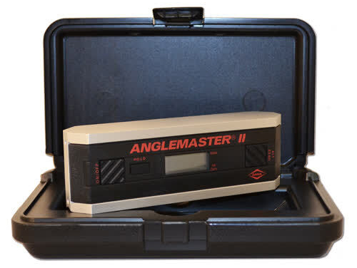
Comments
More from this build


No comments yet.