Home/
Registry/
Ford/
Bronco/
1980–1986/
“That dirty old truck”/
NP-435 Swap
supermotors.net/registry/2742/11274
Album section
NP-435 Swap
From 1983 Ford Bronco “That dirty old truck” — documented by Steve83.
51 photos
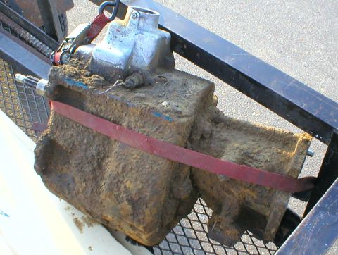
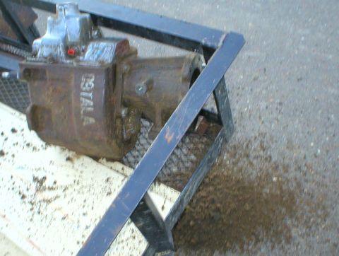
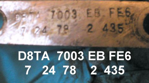
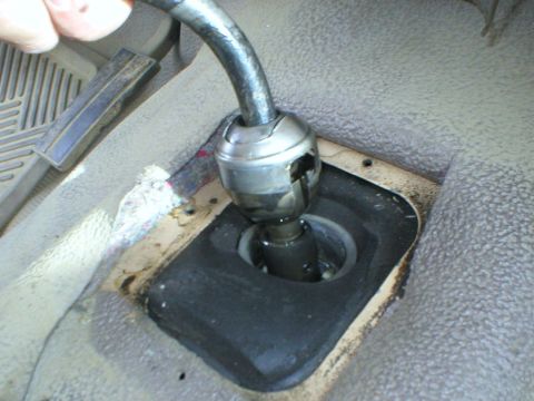
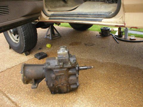
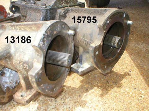
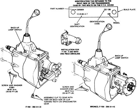
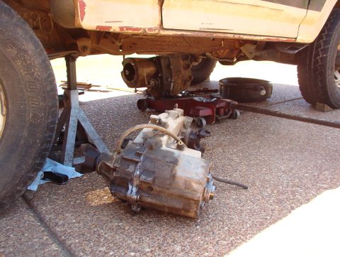
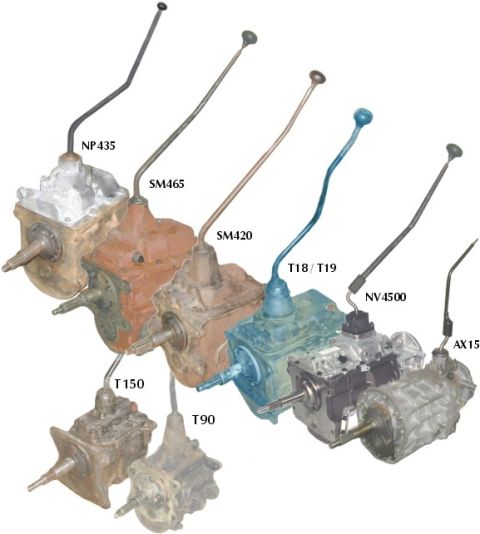
![1983 Ford Bronco - This is the 3rd one going in. See this image for decoding: [url=http://www.supermotors.net/registry/media/72317] http://www.supermotors.net…](https://www.supermotors.net/thumb/72195-480.jpg)
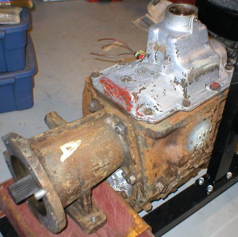
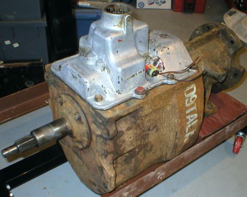
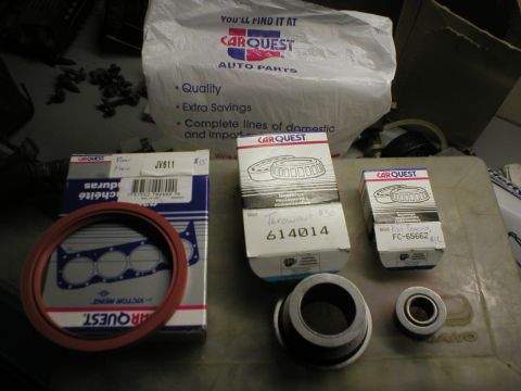
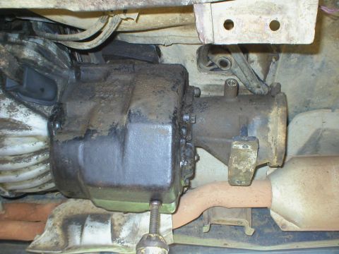
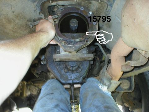
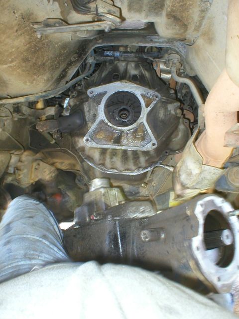
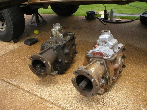
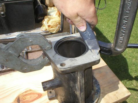
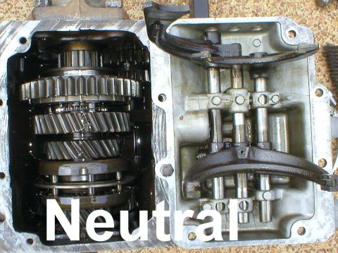
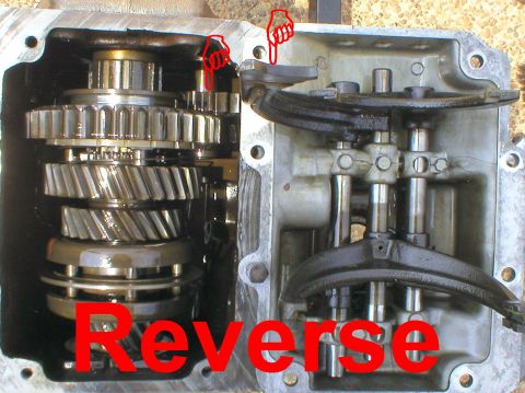
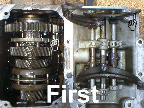
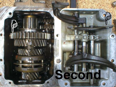
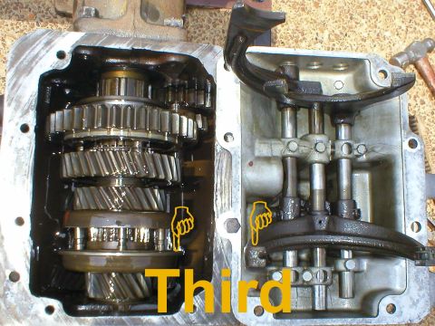
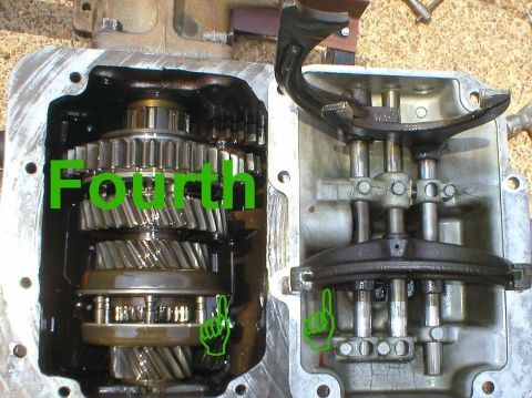
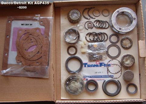
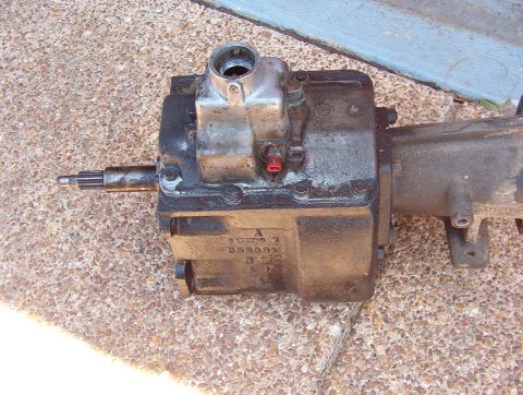
![1983 Ford Bronco - Rebuilding the New Process 435 IF THE IMAGE IS TOO SMALL, click it. [url=http://www.supermotors.net/registry/media/519172] http://www.super…](https://www.supermotors.net/thumb/519922-480.jpg)
Album section
From 1983 Ford Bronco “That dirty old truck” — documented by Steve83.