|
|
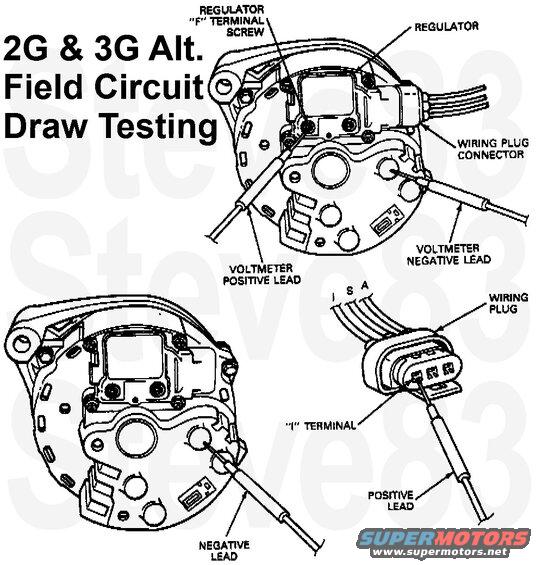
2G & 3G Alternator Field Circuit Draw Testing
IF THE IMAGE IS TOO SMALL, click it.
Connect the voltmeter negative lead to the alternator rear housing for all of the following voltage readings.
1. With the ignition switch turned off, contact the voltmeter positive lead to the regulator F terminal screw. The meter should indicate battery voltage if the system is operating normally. If less than battery voltage is indicated, proceed to Step 2 to find the cause of the current drain.
2. Disconnect the wiring plug from the regulator and contact the voltmeter positive lead to the wiring plug I terminal. No voltage should be indicated. If voltage is indicated, service the I lead from the ignition switch to identify and eliminate the voltage source.
3. If no voltage was indicated in Step 2, contact the voltmeter positive lead to the wiring plug S terminal. No voltage should be indicated. If no voltage is indicated, replace the regulator.
4. If voltage was indicated in Step 3, disconnect the wiring plug from the alternator rectifier connector. Again, contact the voltmeter positive lead to the regulator wiring plug S terminal. If voltage is indicated, service the S lead to the alternator plug to eliminate the voltage source. If no voltage is indicated, replace the alternator rectifier assembly.
B1 - Preliminary Checks
^ Check fuse Link.
^ Check battery terminals and cable clamps.
^ Check wiring and ground connections to alternator regulator and engine.
^ Check alternator belt tension.
^ Are the above items functioning properly?
YES -- Go to B2 - Base Voltage and No Load Test
NO -- Service and/or replace as necessary. Go to B2 - Base Voltage and No Load Test
B2 - Base Voltage and No Load Test
^ Connect voltmeter to battery posts. Read battery voltage - this is base reading.
^ Start engine, run at 1500 rpm with no electrical load. Voltage should increase but not more than 2.0 volts.
Increased, but not more than 2.0 volts? -- Go to B3 - Load Test
No increase? -- Go to B5 - Under Voltage Test
Increases more than 2.0 volts? -- Go to B12 - Over Voltage Test
B3 - Load Test
^ Increase engine speed to 2000 rpm.
^ Turn heater-A/C blower on high and headlamps on high beam.
^ Voltage should read a minimum of 0.5 volt over base voltage.
Increases 0.5 volt or more -- Go to B4 - Batt Drain With Key Off
Increases less than 0.5 volt -- Go to B5 - Under Voltage Test
B4 - Batt Drain With Key Off
^ Problem can still be battery drain. Turn off ignition, install test lamp in series with positive battery cable and check to isolate problem circuit.
^ Is there battery drain?
YES -- Check vehicle circuits for drain.
NO -- Visually inspect battery and perform load test.
B5 - Under Voltage Test
^ Disconnect regulator.
^ Check resistance between regulator A and F terminals.
^ Resistance should be more than 2.4 ohms.
2.4 ohms or less -- Replace regulator. Check alternator for shorted field circuit and service if required. Go to B2 - Base Voltage and No Load Test
More than 2.4 ohms -- Go to B6 - A Terminal Voltage Check
B6 - A Terminal Voltage Check
^ Reconnect regulator.
^ Measure A terminal voltage.
No voltage -- Service A circuit wiring.
Battery voltage -- Go to B7 - F Terminal Voltage Check With Key Off
B7 - F Terminal Voltage Check With Key Off
^ Measure regulator F terminal voltage with ignition off.
No voltage -- Service IAR for open or grounded field circuit. Go to B2 - Base Voltage and No Load Test
Battery voltage -- Go to B8 - F Terminal Voltage Check With Key On
B8 - F Terminal Voltage Check With Key On
^ Turn ignition on, but do not start engine.
^ Measure regulator F terminal voltage.
More than 1.5 volts -- Go to B9 - I Circuit Tests
1.5 volts or less -- Go to B10 - Jumpered Load Test
B9 - I Circuit Tests
^ Perform I circuit tests.
^ I circuit tests OK?
YES -- Replace regulator. Go to B2 - Base Voltage and No Load Test
NO -- Service vehicle I circuit wiring. GO to B2 - Base Voltage and No Load Test
B10 - Jumpered Load Test
^ Disconnect alternator plug.
^ Connect jumper wires between B blades and wiring plug.
^ Repeat load test measuring voltage to jumper wires from battery negative clamp.
^ Voltage should rise 0.5 volt or more.
Voltage rise 0.5 volt or more -- Service alternator to starter relay wiring. Go to B2 - Base Voltage and No Load Test
Voltage rise less than 0.5 volt -- Go to B11 - Load Repeat (F Terminal)
B11 - Load Repeat (F Terminal)
^ Keep B jumper wires in place.
^ Connect another jumper wire from alternator rear housing to regulator F terminal.
^ Repeat load test measuring voltage at B jumper wires.
^ Voltage should rise 0.5 volt or more.
Voltage rise 0.5 volt or more -- Replace regulator. Go to B2 - Base Voltage and No Load Test
Voltage rise less than 0.5 volt -- Service alternator. Go to B2 - Base Voltage and No Load Test
B12 - Over Voltage Test
^ Turn ignition on, but do not start the engine.
^ Measure voltage at regulator A terminal and starter solenoid.
^ Voltage difference should be 0.5 volt or less.
Voltage difference 0.5 volt or less -- Go to B13 - Regulator Ground Check
Voltage difference more than 0.5 volt -- Service A circuit wiring. Go to B2 - Base Voltage and No Load Test
B13 - Regulator Ground Check
^ Check for loose regulator ground screws.
YES -- Service loose ground screws. Go to B2 - Base Voltage and No Load Test
NO -- Go to B14 - Eng Ground Check
B14 - Eng Ground Check
^ Check for bad engine ground.
YES -- Service engine ground. Go to B2 - Base Voltage and No Load Test
NO -- Go to B15 - Alternator Ground Check
B15 - Alternator Ground Check
^ Check alternator ground.
^ Is alternator ground OK?
YES -- Go to B16 - Repeat No Load Test
NO -- Service alternator ground. Go to B2 - Base Voltage and No Load Test
B16 - Repeat No Load Test
^ Start engine, run at 1500 rpm with no electrical load. Voltage should increase not more than 2.0 volts.
Increases 2.0 volts or less -- Go to B3 - Load Test
Increases more than 2.0 volts -- Go to B17 - A and F Voltage Checks
B17 - A and F Voltage Checks
^ Turn ignition off.
^ Measure voltage at regulator A and F terminals.
^ Both terminals should measure battery voltage.
Battery voltage -- Replace regulator. Go to B2 - Base Voltage and No Load Test
Different than battery voltage -- Service integral assembly for grounded field circuit or bad regulator. Go to B2 - Base Voltage and No Load Test
|