A/C clutch cycling diagnostic flowchart from a 1989 TSB
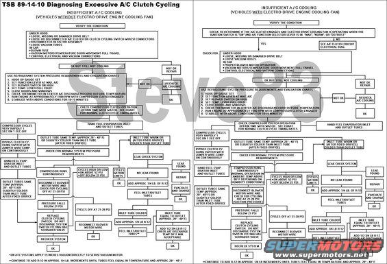
TSB 89-14-10 A/C Clutch Cycling Diagnosis
IF THE IMAGE IS TOO SMALL, click it.
ISSUE: Poor air conditioning cooling caused by low or no refrigerant charge often results in unnecessary replacement of the clutch cycling pressure switch. The switch is designed to work on system pressure. It closes at about 46 psi and opens at about 24.5 psi. It has a normal cycle (on and off) rate of 2 to 5 cycles per minute.
ACTION: If an inoperative or fast cycling pressure switch is found, use the following diagnostic charts before replacing the pressure switch.
DIAGNOSTIC PROCEDURE:
1. Connect a manifold gauge set to the service ports and check the system pressures. They should be above the closing pressure of the switch (46 psi).
2. If the A/C system pressures are above 46 psi and the clutch will not engage, proceed as follows:
> Check the pressure switch harness connector and harness wires for a continuous open condition.
> Check for an intermittent open or a poor connection between the connector and the pressure switch terminals.
a. If the harness connector and wire are OK, by-pass the pressure switch by jumping the two terminals of the connector. If the clutch still does not engage, THE PRESSURE SWITCH IS NOT DEFECTIVE. Refer to the respective EVTM for the clutch circuit schematic and circuit diagnosis. Repair as necessary.
3. Check the ambient temperature. If the ambient temperature is below 48° F (9° C), the system pressure will not be high enough to close the pressure switch (46 psi).
4. If the system does not contain refrigerant, the pressure will not be high enough to close the switch for compressor operation. Leak test, repair, evacuate and charge the system.
5. If the pressures are above 46 psi and the clutch cycle rate is faster than the normal rate of 2 to 5 cycles per minute, the system is probably low on refrigerant. Check that the system contains the correct refrigerant charge by following the correct diagnostic chart.
For more info, see this:
For other TSBs, check here.
--------------------------------------------------------------------------------
TSB 91-20-12 A/C Pressure Relief Leak
Publication Date: OCTOBER 2, 1991
LIGHT TRUCK: 1987-91 BRONCO, F-150-350 SERIES
1988-91 F SUPER DUTY, F-47
ISSUE: There may be a loss of A/C refrigerant through the A/C compressor high relief valve during idle and stop-and-go traffic conditions. Eventually, there may be a lack of cooling and oil stains may appear around the A/C compressor high pressure relief valve.
The excessive discharge pressure is caused by the recirculation of higher temperature engine compartment air passing through the condenser during idle and stop-and-go traffic conditions. Normally, cooler ambient air passes through the condenser. Since the refrigerant in the condenser cannot be sufficiently cooled by this high temperature air, excessive head pressures are created causing refrigerant to be vented through the high pressure relief valve.
ACTION: Replace the radiator lower air shield, located between the lower radiator support and the front bumper, with a new radiator lower air deflector ( F1TZ-8327-B ). This new air deflector is larger than the old air shield and will minimize the amount of hot air recirculation through the condenser. Refer to the 1991 Bronco, Econoline, F-Series, F-Super Duty Truck Shop Manual, Section 01-08, for service details.
NOTE: TO REPLACE THE DEFLECTOR ON OLDER VEHICLES, IT WILL BE NECESSARY TO DRILL HOLES, FOLLOWING THE HOLE PATTERN IN THE NEW DEFLECTOR, BEFORE IT CAN BE ATTACHED.
PART NUMBER PART NAME
F1TZ-8327-B Radiator Lower Air Deflector
OTHER APPLICABLE ARTICLES: NONE
SUPERSEDES: 91-14-13
WARRANTY STATUS: Eligible Under Basic Warranty Coverage
OPERATION DESCRIPTION TIME
912012A Install New Air Deflector 0.4 Hr.
--------------------------------------------------------------------------------
TSB 94-19-20 R-134a Charge
Publication Date: SEPTEMBER 21, 1994
LIGHT TRUCK: 1994-95 BRONCO, F-150-350 SERIES, F-47
ISSUE: Ford Climate Control Division has increased the refrigerant charge in the subject vehicles from 2 lbs. 1 oz. to 2 lbs. 6 ozs.
ACTION: When service to the A/C system is required, recharge the A/C system with 2 lbs. 6 oz. of R-134a. Make the necessary corrections to the 1994-95 Service Manuals, pages 12-00-35, 12-03A-58 for 1994 and 12-00-39, 12-03A-56 for 1995.
Obtain an Authorized Modifications Decal and list the date, dealer number, and summary of alterations performed. Select a prominent place adjacent to the Vehicle Emission Control Information Decal suitable for installing the Authorized Modifications Decal. Clean the area, install the decal, and cover it with a clear plastic decal shield.
OTHER APPLICABLE ARTICLES: NONE
WARRANTY STATUS: INFORMATION ONLY
'80-96 F-series & Broncos w/R-134a take 7oz of PAG-46.
--------------------------------------------------------------------------------
TSB 93-8-13 Replacement A/C Vacuum Reservoir
Publication Date: APRIL 14, 1993
LIGHT TRUCK: 1992-93 BRONCO, F-150-350 SERIES
ISSUE: The vacuum tank for the heater or heater/air conditioning controls is sonically welded to the side of the heater or evaporator case. If a vacuum leak occurs at the vacuum tank, a different vacuum tank can be used to make the repair without removing the old vacuum tank.
ACTION: Install a new service vacuum tank. Refer to the following procedure for service details.
SERVICE PROCEDURE
1. In the engine compartment, detach the vacuum hose from the sonically welded vacuum tank on the heater or evaporator case.
2. Attach the replacement vacuum tank (F3TZ-19D848-A) in a conveniently located spot that can be reached by the vacuum hose. Several areas are available:
a. On the old sonically welded tank, drill an appropriate size hole in the old vacuum tank and use a self-tapping screw to attach the new replacement vacuum tank. The replacement vacuum tank (F3TZ-19D848-A) has slots which will accept the screws.
b. Attach the replacement vacuum tank and put on the vacuum hose.
3. If the old tank mount location is not suitable, locate an existing screw on the blower case and put the replacement vacuum tank (F3TZ-19D484-A) with its slotted bracket in a position over the screw.
a. Make sure of the following points:
* There is room for the tank.
* The vacuum hose will reach it.
* The replacement tank can be attached with that screw.
b. If necessary, rework the slot on the replacement vacuum tank so the screw will fit through it.
c. Attach the replacement vacuum tank and put on the vacuum hose.
4. Verify that the system operates properly.
PART NUMBER PART NAME
F3TZ-19D848-A Vacuum Tank
OTHER APPLICABLE ARTICLES: NONE
WARRANTY STATUS: Eligible Under Bumper To Bumper Warranty Coverage
OPERATION DESCRIPTION TIME
930813A Install Replacement Vacuum Tank 0.3 Hr.
See also:
Is this accurate? Sign in to help verify it.
Comments
More from this build


No comments yet.