Home/
Registry/
Chevrolet/
Silverado 3500/
“BigGoldDuallie SOLD”/
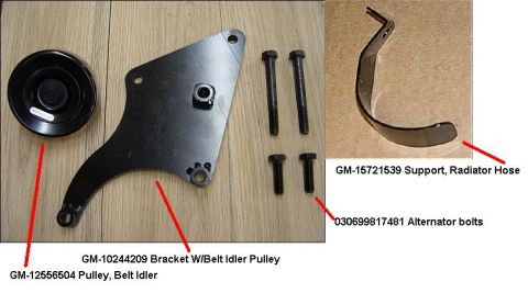
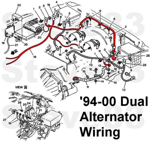
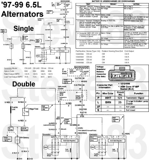
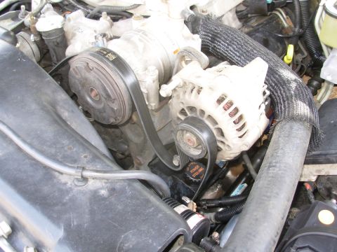
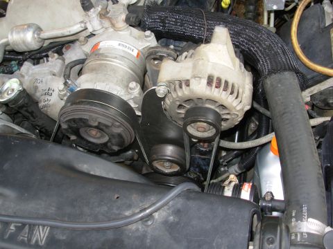
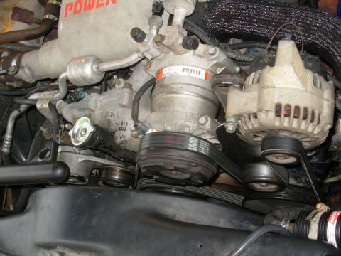
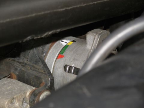
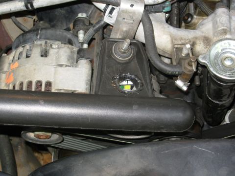
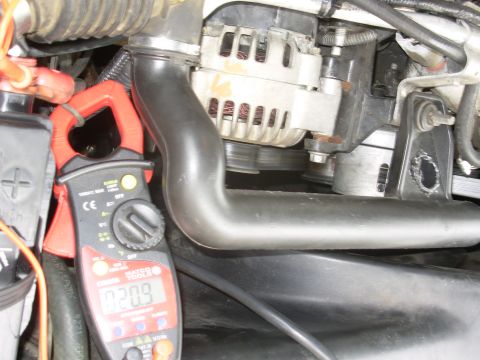
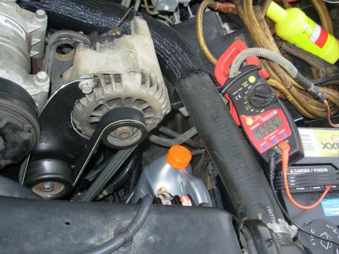
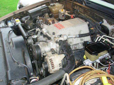
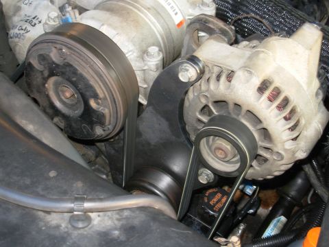
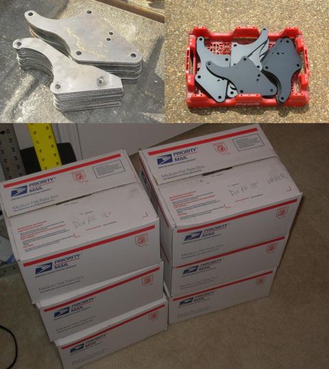
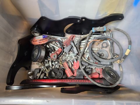
Dual Alternator Bracket
supermotors.net/registry/22771/80319
Album section
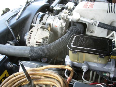
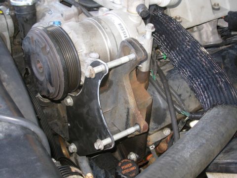
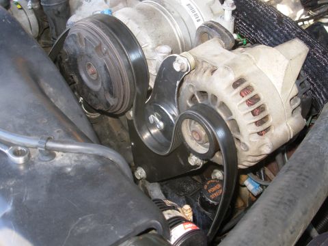
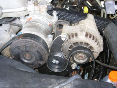
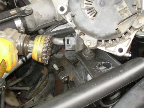
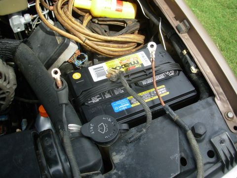
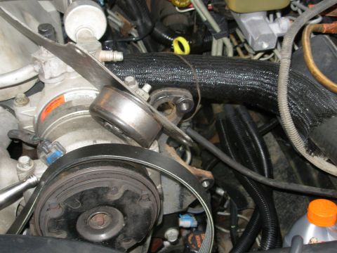
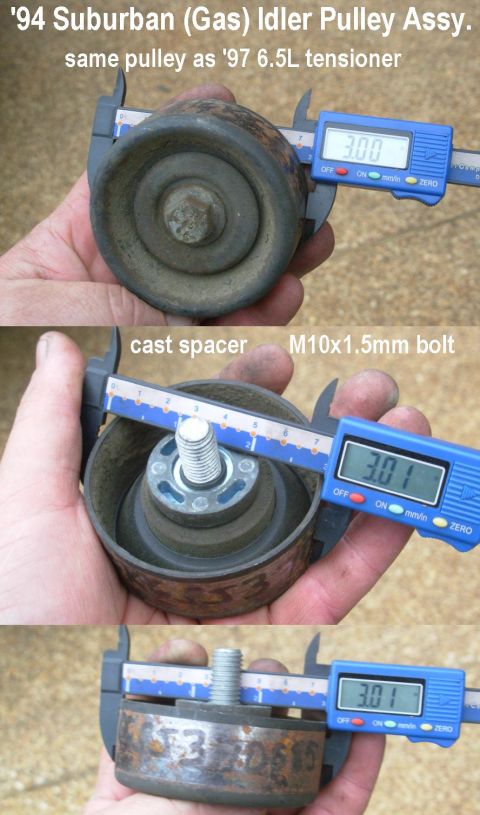
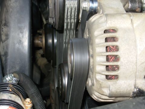
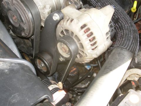
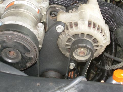
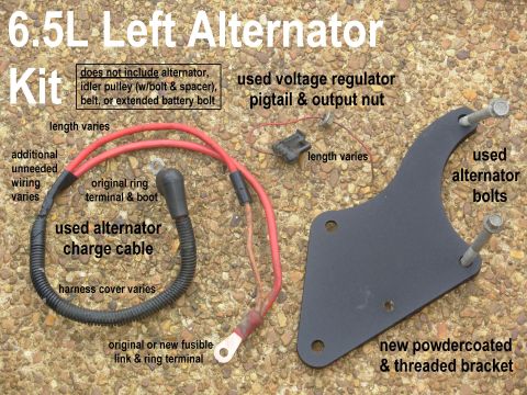
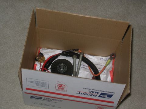
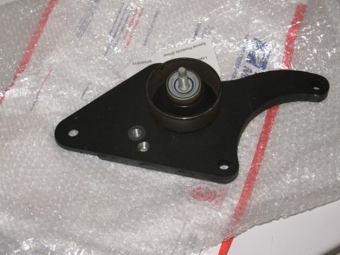
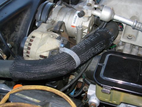
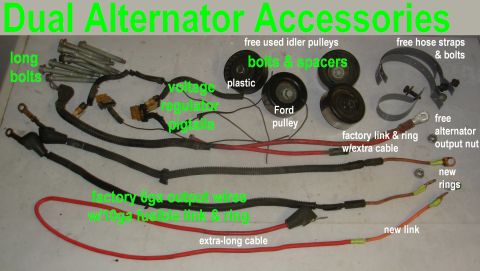
Dual Alternator Bracket
From 1997 Chevrolet Silverado 3500 “BigGoldDuallie SOLD” — documented by Steve83.
30 photos