Share This
Url
Tag
Img
Thumb

TSB97-03-10Fig9.JPG | Hits: 4766 | Size: 26.62 KB | Posted on: 12/21/06 | Link to this image


TSB 
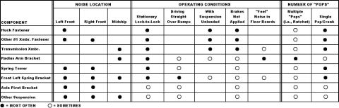
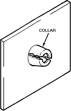
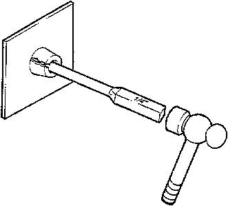
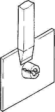
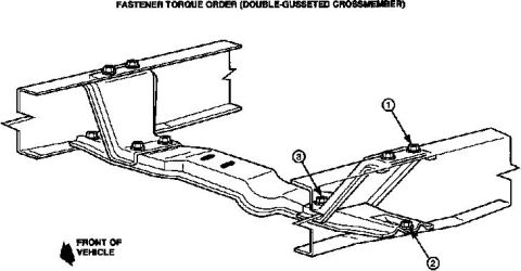
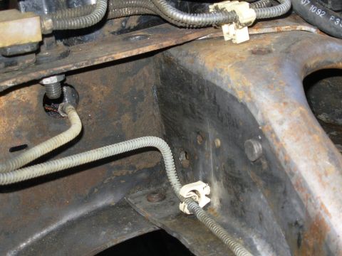
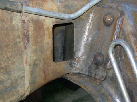
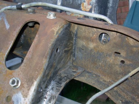
97-03-10 Frame Noise
Publication Date: FEBRUARY 3, 1997
IF THE IMAGE IS TOO SMALL, click it.

LIGHT TRUCK:
1980-96 BRONCO, F-150, F-250 LD
1980-97 F-250 HD, F-350
1988-97 F SUPER DUTY, F-47

This TSB article is being republished in its entirety to include vehicles built through the 1997 model year and to update the Transmission Crossmember Service Procedure.

ISSUE:
A "popping/creaking" sound may come from the area of the front frame or suspension brackets. This may occur because of a slip/stick motion at a loose rivet or bolt in a frame crossmember or a suspension bracket (radius arm, spring tower, spring shackle, etc.).

ACTION:
Use the following Diagnostic Procedure to determine the location of the noise. Replace the suspected fastener(s) by referring to the following Repair Procedure for details.


SOURCES OF VARIOUS FRONT UNDERBODY NOISES

Various front underbody noises may originate from several different sources and are often difficult to locate and diagnose. Common noise locations include:

> #1 (engine) crossmember rivets - primarily the rivet or "huck fastener" at the lower left front, behind the steering gear
> loose or improperly seated spring shock tower rivets/bolts
> loose or misaligned transmission crossmembers
> loose or improperly seated front leaf spring bracket rivets
> loose radius arm brackets
> loose axle pivot brackets

Other underbody areas that produce similar noises include:
> transfer case skid plate
> leaf spring bushings
> steering intermediate shafts
> shock bolts
> bumper brackets
> brakes

Other Service Bulletins have been published to address the proper repair of these concerns.


DIAGNOSTIC PROCEDURE

1. INTERVIEW THE CUSTOMER

a. Understand the customer's description of the noise and of the conditions under which it is heard.

b. Road test the vehicle with the customer to fully understand where, how, and when the noise occurs.

2. DUPLICATE THE NOISE CONCERN

a. Drive the vehicle around for at least 15 minutes to warm-up and exercise the frame joints so that any frame noise is more likely to be repeatable in the garage or on the road.

b. Identify the conditions in which the noise is repeatable. Does the noise occur:
> While parked and turning the wheels lock-to-lock?
> Only when driving?
> While going straight over bumps?
> While on a lift with the suspension unloaded?
> Only when the brakes are applied?

c. Identify the general location of the noise. Can you "feel" the noise in the floorboard or the steering wheel? Refer to Figure 9 for likely locations for the noise.

NOTE:
USE CHASSIS EARS AND/OR A STETHOSCOPE TO DETERMINE THE LOUDEST POINT OF THE NOISE. IF THE NOISE IS REPRODUCIBLE WHEN STATIONARY, PUT THE VEHICLE ON A DRIVE-ON LIFT AND "FEEL" FOR ANY MOVEMENT OR VIBRATION AT THE JOINTS.

Click "Next" beside the image above to continue.

See also:
http://www.nloc.net/vbforum/gen-1-lightnings/209927-frame-off-resto-225k-mile-lighting-2.html#post1958385
. . .

Share This
Url
Tag
Img
Thumb

TSB97-03-10Fig1.JPG | Hits: 2825 | Size: 12 KB | Posted on: 12/21/06 | Link to this image


3. INSPECT FRAME BOLTS FOR PROPER INSTALLATION TORQUE

Inspect and tighten all front end components which bolt to the frame to confirm that they are at the proper torque (refer to the Repair Procedure section of this article for proper torque requirements). This includes, but is not limited to:

> radius arm bracket bolts
> axle pivot bracket bolts
> transmission crossmember bolts
> spring tower bolts

4. INSPECT THE FRAME RIVETS
> Inspect all riveted frame and suspension components in the general area of the noise for loose or improperly seated rivets.

NOTE:
TAP THE RIVETS WITH A SMALL HAMMER. WHEN A RIVET IS NOT INSTALLED PROPERLY IT WILL MAKE A DIFFERENT SOUND THAN A "SNUG" RIVET.

> Service identified rivets according to the procedure listed in the Repair Procedure section.

5. TEST DRIVE THE VEHICLE

Road test the vehicle again to duplicate the concern. If the noise is still present, proceed to the next Step.

6. TEST JOINTS TO LOCATE NOISE
> Use a small pry bar as a "wedge" between components suspected of causing the noise. By pounding the wedge into a joint or behind a bracket, the noise should change or be eliminated if the noise is coming from that location.

NOTE:
USING A STETHOSCOPE, OR CHASSIS EARS, WILL HELP TO IDENTIFY ANY NOISE CHANGE.

> If the source of the noise is identified, proceed to the Repair Procedure section.
> If the source of the noise has not been identified by this Step, investigate other non-frame or suspension sources and/or proceed to the next Step.

7. SERVICE THE VEHICLE

a. If the noise has been identified, proceed to the specific component section in the Repair Procedure.

b. If the noise source has not been identified, refer to Figure 9 for general noise locations, operating conditions and number of occurrences. Proceed with repairing the identified components.


REPAIR PROCEDURE - (A) THROUGH (H)


(A) "Huck Fastener" - Lower Left Front #1 Crossmember Rivet Replacement

This procedure should be done on flat ground or on a drive-on lift, with the wheels pointed straight and full weight resting on the wheels. This fastener could be either a standard cold head rivet in light duty applications or a large "huck" bolt which has the appearance of a large "pop" rivet.

NOTE:
USE WARRANTY DEALER CODING: 5020, AS BASIC PART NO.

1. Remove damaged or loose rivet:

COLD HEAD RIVETS:

> Drill a 3.175mm (1/8") hole through the rivet.
> Redrill the same hole through the shank of the rivet with a 9.525mm (3/8") drill.
> Remove the rivet head with an air chisel.
> Drive out the rivet with a punch and hammer.

"HUCK" RIVETS:

> Use a flat chisel and hammer (or air chisel) to split the exposed collar of the huck fastener (Figure 1).

Click "Next" beside the image above to continue.

See also:
http://www.nloc.net/vbforum/gen-1-lightnings/209927-frame-off-resto-225k-mile-lighting-2.html#post1958385
. . .

Share This
Url
Tag
Img
Thumb

TSB97-03-10Fig2.JPG | Hits: 2295 | Size: 11.36 KB | Posted on: 12/21/06 | Link to this image


Knock the rivet pin out of the blind side with a 6.35mm (1/4") drift punch and hammer (Figure 2).

Click "Next" beside the image above to continue.

See also:
http://www.nloc.net/vbforum/gen-1-lightnings/209927-frame-off-resto-225k-mile-lighting-2.html#post1958385
. . .

Share This
Url
Tag
Img
Thumb

TSB97-03-10Fig3.JPG | Hits: 2236 | Size: 11.01 KB | Posted on: 12/21/06 | Link to this image


> Cut the rivet's head off with a hammer and flat chisel (Figure 3).

Click "Next" beside the image above to continue.

See also:
http://www.nloc.net/vbforum/gen-1-lightnings/209927-frame-off-resto-225k-mile-lighting-2.html#post1958385
. . .

Share This
Url
Tag
Img
Thumb

TSB97-03-10Fig4.JPG | Hits: 2244 | Size: 10.02 KB | Posted on: 12/21/06 | Link to this image


> Knock the sleeve out of the blind side with a 9.525mm (3/8") drift punch and hammer (Figure 4).

CAUTION:
DO NOT REMOVE THE FASTENER WITH A CUTTING TORCH BECAUSE DAMAGE TO THE FRAME STRUCTURE IS LIKELY TO RESULT.

Click "Next" beside the image above to continue.

See also:
http://www.nloc.net/vbforum/gen-1-lightnings/209927-frame-off-resto-225k-mile-lighting-2.html#post1958385
. . .

Share This
Url
Tag
Img
Thumb

TSB97-03-10Fig5.JPG | Hits: 2960 | Size: 41.32 KB | Posted on: 12/21/06 | Link to this image


2. After removing the rivet, verify the noise came from this location by pounding a wedge between the crossmember and the frame liner, then driving the vehicle to reproduce the noise. The wedge will lift the crossmember off of the inner frame liner and eliminate any noise if the lower left front #1 crossmember joint is the source of the noise.

3. With the wedge still in place, insert the Bearing Strip (F6TZ-5D033-BA) between the #1 crossmember and frame liner. Align the strip approximately centered and extending well past the hole location. Remove the wedge and drill a 11.113mm (7/16") diameter hole through the bearing strip.

4. Line ream the existing hole through the liner, frame flange and crossmember to 14.288mm (9/16") (Figure 5). Remove any burrs after reaming.

NOTE:
TO PROPERLY REAM THE HOLE ON A VEHICLE WITH LEAF SPRINGS, THE SPRING MUST BE REMOVED TO PROVIDE VERTICAL ACCESS TO THE RIVET HOLE.

Click "Next" beside the image above to continue.

See also:
http://www.nloc.net/vbforum/gen-1-lightnings/209927-frame-off-resto-225k-mile-lighting-2.html#post1958385
. . .

Share This
Url
Tag
Img
Thumb

TSB97-03-10Fig6.JPG | Hits: 2649 | Size: 42.73 KB | Posted on: 12/21/06 | Link to this image


IF THE IMAGE IS TOO SMALL, click it.
5. Install a 9/16" Grade 8 torque prevailing Nut (34990-S2) with a Washer (44880-S2) and a Grade 8 Bolt (58698-S2) with a Washer (44880-S2) (Figure 6).

Click "Next" beside the image above to continue.

See also:
http://www.nloc.net/vbforum/gen-1-lightnings/209927-frame-off-resto-225k-mile-lighting-2.html#post1958385
. . .

Share This
Url
Tag
Img
Thumb

TSB97-03-10Fig7.JPG | Hits: 3058 | Size: 29.33 KB | Posted on: 12/21/06 | Link to this image


a. Slide the bolt and washer into the "window" opening on the outside of the frame siderail, and insert it into the newly-reamed hole.

NOTE:
ON VEHICLES WITH QUAD SHOCK ABSORBERS, IT MAY BE NECESSARY TO REMOVE THE SHOCK/SPRING TOWER TO GAIN ACCESS TO THE "WINDOW" IN THE SIDERAIL.

b. Install the washer and nut and torque nut to 190 ±4N-m (140 ±3 lb-ft). Turn the wheels lock-to-lock several times to seat the joint and retorque. Tack weld the nut to the bolt after tightening.

CAUTION:
DO NOT WELD THE NUT/WASHER TO THE FRAME.

NOTE:
ON HEAVY DUTY VEHICLES, IT MAY BE NECESSARY TO UPGRADE THE REPLACEMENT FASTENER TO A 5/8" GRADE 8 TORQUE PREVAILING NUT (34991-S2), BOLT (58720-S100) AND TWO (2) WASHERS (44881-S2) TORQUED TO 250 ±6.8 N-m (185 ±5 LB-FT).


(B) Other #1 Crossmember Rivets

NOTE:
USE WARRANTY DEALER CODING: 5020, AS BASIC PART NO.

Follow the "Huck Fastener"/Repair Procedure A, listed in this article for cold head rivets and replace the rivet with a 9/16" Grade 8 torque prevailing Nut (34990-S2) with a Washer (44880-S2) and a Grade 8 Bolt (58698-S2) with a Washer (44880-S2).


(C) Other Rivets

NOTE:
USE WARRANTY DEALER CODING: 5004, AS BASIC PART NO.

Follow TSB «96-15-11» for proper rivet replacement procedure.


(D) Transmission Crossmember

NOTE:
USE WARRANTY DEALER CODING: 5060, AS BASIC PART NO.

This procedure should be done on flat ground or on a drive-on lift, with the wheels pointed straight and full weight resting on the wheels.

NOTE:
A SIMILAR NOISE CAN OCCUR AT THE TRANSFER CASE SKID PLATE ATTACHMENTS AND SHOULD BE INVESTIGATED IN CONJUNCTION WITH THIS REPAIR PROCEDURE.

1. Remove transmission weight:

a. Remove bolts attaching transmission mount to the crossmember.

b. Lift the transmission to remove any load to the crossmember. The crossmember should now be completely loose.

NOTE:
YOU MAY NOTICE THE FRAME RAILS TWIST SLIGHTLY AND "RELAX" AFTER THIS NEXT STEP.

2. Loosen crossmember:

a. Loosen all bolts attaching the crossmember to the frame siderails.

b. Loosen all bolts attaching the crossmember gusset(s) to the crossmember and to the frame siderails. The crossmember should now be completely loose.

3. Turn the steering wheel lock-to-lock and then straighten the wheels. This helps to remove any stress in the frame.

4. Install new crossmember fastening hardware one at a time and replace each nut and bolt with a new Nut (N800937-S427) and Bolt (N802114-S2) and leave them loosely assembled until all crossmember and gusset fasteners have been replaced.

NOTE:
IT IS IMPERATIVE THAT THE FOLLOWING TIGHTENING SEQUENCE BE FOLLOWED.

5. Secure the crossmember attaching hardware. Determine which style of crossmember the vehicle is equipped with, and follow Step 6 or 7.

6. If the vehicle has a wraparound-style crossmember (Figure 7), torque each grouping of fasteners in the order listed in the following Substeps to 70 ±10.5 N-m (52 ±8 lb-ft).

Click "Next" beside the image above to continue.

See also:
http://www.nloc.net/vbforum/gen-1-lightnings/209927-frame-off-resto-225k-mile-lighting-2.html#post1958385
. . .

Share This
Url
Tag
Img
Thumb

TSB97-03-10Fig8.JPG | Hits: 2306 | Size: 30.35 KB | Posted on: 12/21/06 | Link to this image


a. Torque all three (3) bolts/nuts at the crossmember-to-frame siderail at the wraparound side (Figure 7, Number 1).

b. Torque the gusset-to-frame bolts (Figure 7, Number 2).

c. Torque the crossmember-to-frame bolts (Figure 7, Number 3).

d. Torque the gusset-to-crossmember bolts (Figure 7, Number 4).

7. If the vehicle has a double-gusseted crossmember (Figure 8 ), torque each grouping of fasteners in the order listed in the following Substeps to 70 ±10.5 N-m (52 ±8 lb-ft) and repeat for the other side.

Click "Next" beside the image above to continue.
. . .

Share This
Url
Tag
Img
Thumb

TSB97-03-10Chart1.JPG | Hits: 2476 | Size: 24.66 KB | Posted on: 12/21/06 | Link to this image


a. Torque the gusset-to-frame bolts (Figure 8, Number 1).

b. Torque the crossmember-to-frame bolts (Figure 8, Number 2).

c. Torque the gusset-to-crossmember bolts (Figure 8, Number 3).

8. Reattach transmission:

a. Lower the transmission.

b. Reattach the transmission using new Nuts (N621945-S2) and torque to 95 ±15 N-m (70 ±11 lb-ft).

9. Inspect gusset/crossmember joint:

a. Visually inspect the joint between the gusset and crossmember. If all fasteners have been torqued properly and any gap exists between the two, shim joint with washers.

b. Reattach the gusset with new Bolts (N802114-S2) and Nuts (N800937-S427) torqued to 70 ±10.5 N-m (52 ±7 lb-ft).

NOTE:
ON HEAVY DUTY VEHICLES, IT MAY BE NECESSARY TO UPGRADE THE REPLACEMENT FASTENER TO A 9/16" GRADE 8 TORQUE PREVAILING NUT (34990-S2) AND BOLT (58698-S2) TORQUED TO 190 ±4 N-m (140 ±3 LB-FT).


(E) Radius Arm Brackets

NOTE:
USE WARRANTY DEALER CODING: 3B095, AS BASIC PART NO.

1. Inspect and retorque all radius arm bracket bolt(s) to 135 ±20 N-m (100 ±15 lb-ft).

NOTE:
IF THE BOLT IS VERY LOOSE AND THE BRACKET IS NOT CLAMPED TIGHTLY, INSPECT THE FRAME AND BRACKET HOLES FOR ELONGATION. IF A BRACKET HOLE IS ELONGATED, THE BRACKET MUST BE REPLACED. IF A FRAME HOLE IS ELONGATED, THE ENTIRE FRAME MUST BE REPLACED, OR THE FRAME AND BRACKET HOLES MUST BE DRILLED OUT TO A LARGER SIZE, NOT TO EXCEED 15mm (19/32"), AND A LARGER NUT AND BOLT MUST BE INSTALLED.

2. Inspect the rivets for looseness. Replace any loose or poorly seated rivets using the following procedure:

NOTE:
MOST OFTEN, THE NOISE CAN BE ELIMINATED BY REPLACING ONLY THE MIDDLE RIVET OF THE THREE (3) SECURING THE BRACKET.

a. Remove damaged or loose rivet:

> Drill a 3.175mm (1/8") hole through the rivet.

> Redrill the same hole through the shank of the rivet with a 9.525mm (3/8") drill.

> Remove the rivet head with an air chisel.

> Drive out the rivet with a punch and hammer.

CAUTION:
DO NOT REMOVE THE FASTENER WITH A CUTTING TORCH BECAUSE DAMAGE TO THE FRAME STRUCTURE IS LIKELY TO RESULT.

b. Line ream the hole to the replacement bolt size of 12.7mm (1/2").

c. Clean hole of burrs after reaming so that the bolt head and nut will seat properly.

d. Install a new Bolt (N802210-S2) and Nut (N800937-S427), and torque to 133 ±20 N-m (98 ±15 lb-ft).


(F) Spring Towers

NOTE:
USE WARRANTY DEALER CODING: 5A306, AS BASIC PART NO.

Inspect the rivets for looseness. Replace any loose or poorly seated rivets using the following procedure.

1. Remove damaged or loose rivet:

a. Drill a 3.175mm (1/8") hole through the rivet.

b. Redrill the same hole through the shank of the rivet with a 9.525mm (3/8") drill.

c. Remove the rivet head with an air chisel.

d. Drive out the rivet with a punch and hammer.

CAUTION:
DO NOT REMOVE THE FASTENER WITH A CUTTING TORCH BECAUSE DAMAGE TO THE FRAME STRUCTURE IS LIKELY TO RESULT.

2. Line ream the hole to the replacement bolt size of 11.113mm (7/16").

3. Clean hole of burrs after reaming so that the bolt head and nut will seat properly.

4. Install a new Bolt (56561-S2) and Nut (382400-S2), and torque to 89 ±13 N-m (66 ±10 lb-ft).


(G) Front Leaf Spring Brackets

NOTE:
USE WARRANTY DEALER CODING: 5340, AS BASIC PART NO.

Inspect the rivets for looseness. Replace any loose or poorly seated rivets using the following procedure.

1. Remove damaged or loose rivet:

a. Drill a 3.175mm (1/8") hole through the rivet.

b. Redrill the same hole through the shank of the rivet with a 8.731mm (11/32") drill.

c. Remove the rivet head with an air chisel.

d. Drive out the rivet with a punch and hammer.

CAUTION:
DO NOT REMOVE THE FASTENER WITH A CUTTING TORCH BECAUSE DAMAGE TO THE FRAME STRUCTURE IS LIKELY TO RESULT.

2. Install a new Bolt (58634-S2), two (2) Washers (44877-S2) and a Nut (34987-S2). Torque to 62 ±15 N-m (46 ±11 lb-ft).


(H) Axle Pivot Brackets

NOTE:
USE WARRANTY DEALER CODING: 3B178, AS BASIC PART NO.

Inspect and retorque all axle pivot bracket bolts (torque values may vary by model - refer to the appropriate light truck Service Manual for proper torque specifications).

NOTE:
IF THE BOLT IS LOOSE AND THE BRACKET IS NOT CLAMPED TIGHTLY, INSPECT THE FRAME AND BRACKET HOLES FOR ELONGATION. IF A FRAME HOLE IS ELONGATED, THE ENTIRE FRAME MUST BE REPLACED. NO FRAME REPAIRS ARE AUTHORIZED ON THESE #1 CROSSMEMBER HOLES.

OTHER APPLICABLE ARTICLES:
96-15-11
SUPERSEDES: 96-4-11

WARRANTY STATUS: Eligible Under The Provisions Of Bumper To Bumper Warranty Coverage For 1992-96 Model Years, Basic Warranty Coverage For All Others


Click "Next" beside the image above to continue.

See also:
http://www.nloc.net/vbforum/gen-1-lightnings/209927-frame-off-resto-225k-mile-lighting-2.html#post1958385
. . .

Share This
Url
Tag
Img
Thumb

TSB97-03-10Chart2.JPG | Hits: 2131 | Size: 82.21 KB | Posted on: 12/21/06 | Link to this image


Warranty LABOR ALLOWANCE

Click "Next" beside the image above to continue.

Share This
Url
Tag
Img
Thumb

TSB97-03-10Chart3.JPG | Hits: 2139 | Size: 24.18 KB | Posted on: 12/21/06 | Link to this image


DEALER CODING
OASIS CODES: 305000, 390000, 702000, 702100

If viewing a single image per page, click "Next" beside the image above to continue.

SEE ALSO:

. .

Share This
Url
Tag
Img
Thumb

90Xmbr1WeldLHR.JPG | Hits: 1863 | Size: 95.18 KB | Posted on: 5/6/12 | Link to this image


Factory welds in a '93 Bronco #1 (engine) crossmember LHR.

Share This
Url
Tag
Img
Thumb

90Xmbr1WeldRHF.JPG | Hits: 1585 | Size: 88.94 KB | Posted on: 5/6/12 | Link to this image


Factory welds in a '93 Bronco #1 (engine) crossmember RHF.

Share This
Url
Tag
Img
Thumb

90Xmbr1WeldRHR.JPG | Hits: 1716 | Size: 97 KB | Posted on: 5/6/12 | Link to this image


Factory welds in a '93 Bronco #1 (engine) crossmember RHR.


About SuperMotors | Contact Us | FAQ/Help | Legal
Copyright © 1998-2024 Web Design Solutions, Inc.
All rights reserved. Duplication & reproduction is strictly prohibited.
SuperMotors.net v5.0.2 ChangeLog