Bulb, Fuse, & Wire Current Specs
For bulb resistance, use Ohm's law: V (Volts) = R (Ohms) x i (Amps), so:
R (Ohms) = V (Volts) / i (Amps)
A 194 bulb has 14 / .72 = 19.4444444 Ohms resistance
An 1815 bulb has 14.4 / 0.2 = 72 Ohms resistance
For an incandescent bulb labeled in volts & watts: V x V / W = R
A 15W @ 12V bulb has 12 x 12 / 15 = 9.6 Ohms
- When the diameter of a wire is doubled, the AWG will decrease by 6. (e.g., No. 18 AWG is about twice the diameter of No. 24 AWG.)
- When the cross-sectional area of a wire is doubled, the AWG will decrease by 3. (e.g., two No. 18 AWG wires have about the same cross-sectional area as a single No. 15 AWG wire.)
- When gauge is decreased by ten gauge numbers (from No. 18 to 8 ), the area and weight increase, and the resistance decreases, each by a factor of approximately 10.
Most commonly-available wire has PVC insulation. Wire labelled for use as fusible link has cross-linked polyethylene insulation (XLPE). The modern name for XLPE is PEX.
See also:

.

.

.
 https://www.fleet.ford.com/truckbbas/non-html/2002/281.pdf https://www.fleet.ford.com/truckbbas/non-html/1997/c37_39_p.pdf
-----------------------------------------------------------
ELECTRICAL MODIFICATIONS:
1. All wiring additions and revisions should comply with procedures described below.
2. If horns are relocated, their location must be above the frame bottom with the bell mouth of each horn pointed down.
3. If the battery location is changed, the new location must be adequately ventilated, accessible for servicing, protected from road splash, and incorporate a shockless mounting.
4. If the battery location is changed requiring longer cables, a heavier wire gauge battery cable must be used.
5. If the original-equipment battery is replaced by more than one battery or a battery of a larger capacity, the battery charging and power supply circuit must be checked and revised to carry the additional loads.
6. Fog and driving lamps: state, provincial or local laws may regulate the manner in which the fog and driving lamps are used, or may require additional equipment for the particular use intended for the vehicle. It is the buyer's/owner's/operator's responsibility to determine the applicability of such laws to the intended use for the vehicle, and to arrange for the installation of required equipment.
7. Do not delete or deactivate the Center High Mount Stop Lamp unless it will be blocked by second unit body.
8. Adding high-current loading to the electrical system (such as A/C) will require an alternator with a minimum 60 Ampere rating.
Caution: The remote electronic voltage regulator base must always be connected to the battery, engine, and chassis ground when the ignition switch is in either the on or start position. The voltage regulator will be damaged if this connection does not exist when the ignition switch is energized.
ELECTRICAL WIRING SECTION
This section provides instructions for the addition and/or modification of electrical devices to the vehicle electrical system.
GENERAL PRACTICES
Vehicles stored on site should have the negative battery cable disconnected to minimize "Dead Battery" situation. This applies to both "incomplete" and "complete" vehicles in storage.
Federal and Canadian Motor Vehicle Safety Standards (F/CMVSS) Requirements:
1. All Ford vehicles built and fully-completed by Ford comply with FMVSS and CMVSS No. 108, "Lamps, Reflective Devices and Associated Equipment" and other applicable FMVSS and CMVSS that affect electrical components.
2. Incomplete vehicle (i.e., chassis cab, stripped chassis, chassis cowl, etc.) will conform to these F/CMVSS according to the provisions and conditions stated in the Incomplete Vehicle Manual attached to each incomplete vehicle. Care must be taken that modifications do not conceal, alter or change components installed or provided by Ford Motor Company to achieve this conformance.
3. All vehicles powered by spark ignition internal combustion engines (e.g. gasoline or liquid petroleum gas engines) and manufactured for sale or use in Canada are subject to the Canadian "Regulations for the Control of Interference to Radio Reception," SOR / 75-629, Canada Gazette Part II, Vol. 109, No. 21, November 12, 1975, as amended by SOR / 77-860, Canada Gazette Part II, Vol. 111, No. 21, November 9, 1977, by SOR / 78-727, Canada Gazette Part II, Vol. 112, No. 18, September 27, 1978, and by SOR / 80-915, Canada Gazette Part II, Vol. 114, No. 23, December 10, 1980. Violation of these regulations is punishable by fine or imprisonment. Ford-built incomplete vehicles other than stripped chassis are designed and manufactured to be capable of meeting the regulatory requirements or such modifications thereof as may be authorized by the Canadian Department of Communications. However, because Ford has no control over how an incomplete vehicle is completed by subsequent stage manufacturers, Ford does not represent that the completed vehicle incorporating the Ford-built components will comply with applicable requirements.
Routing & Clamping:
1. It is strongly recommended that wiring in areas of heavy rework, or in areas where welding operations are to be performed, be removed prior to the rework operations and reinstalled after the rework is completed. If vehicle is equipped with an Electronic Engine Control System, the EEC module must be disconnected before any electrical welding is performed; otherwise, module damage may result. If wire removal is not practical, the wires must be shielded from damage due to the rework and welding heat. All components and wiring should be re-installed as closely as possible to the factory arrangement.
2. Wires routed through holes in sheet metal or castings must have the hole edges protected by a grommet or edge lacing.
3. Wires should be routed to avoid metal edges, screws, trim fasteners and abrasive surfaces. When such routings are not possible, protective devices (shields, caps, wire loom, etc.) must be used to protect the wires. When wires must cross a metal edge, the edge should be covered with a protective shield, and the wiring secured within three inches on each side of the edge.
4. Wires must be routed to provide at least three inches clearance to moving parts, unless positively fastened or protected by a conduit.
5. Wire routings should avoid areas where temperatures exceed 180�F, and a minimum clearance of six inches should be maintained from exhaust system components. Where compliance with this requirement is not possible, heat insulation and heat shields are required.
6. When wiring is routed between two members where relative motion can occur, the wiring should be secured to each member, with enough wire slack to allow flexing without damage to the wire.
7. Wiring to all circuit components (switches, relays, etc.) in exposed locations must provide a drip loop to prevent moisture from being conducted into the device via the wire connection.
8. Routing wires into areas exposed to wheel wash should be avoided. When such routings cannot be avoided, adequate clipping or protective shields are required to protect the wires from stone and ice damage.
9. Routing wires under the frame side members or at points lower than the bottom frame flange should be avoided to prevent damage to the wires from brush contact in off-road operations.
10. The wire retainers and grommets installed by the assembly plant are usually designed to accommodate only the Ford-installed wires. Additional wiring or tubing should be retained by additional clips. When added wires or tubes are routed through sheet metal panels, new holes (with proper wire protection and sealing) must be used.
11. All wiring connnections to components of the factory-installed system must be accomplished by using the proper mating wire termination. (Connections on studs and ground connections must use eyelet terminations, connections to female bullets must terminate in male bullets, etc. Scotch-Loks and other mechanical pierce connections are not acceptable.)
Splice/Repair:
1.Wire ends should be stripped making sure that individual conductor strands are not damaged. Corrosion of the strands must be cleaned away before splicing.
2. When soldering, make sure an adequate mechanical joint exists before applying solder. Use only rosin-core solder for electrical connections; never acid-core.
3. For crimp joints, use butt-type metal-barrel fasteners and a proper tool (such as Motorcraft crimp tool S-9796) specifically designed for this type of work, and for the size of the crimp.
4. Splice joints must be adequately sealed and insulated (except return/ground circuits). Heat shrink tubing is highly recommended to cover soldered and bare metal-barrel crimp joints. Quality electrical tape can be used inside the vehicle but is not recommended for an outside environment.
5. Seal the ends of insulated barrel crimp devices with a silicone grease or hot glue when in an outside environment.
6. The most-durable splice joint will be bare metal-barrel crimped, flow-soldered, and covered with adhesive shrink tubing. Use this type of joint as often as possible.
Circuit Protection:
1. Modification to existing vehicle wiring should be done only with extreme caution and consideration of effects on the completed vehicle electrical system. Anticipated circuitry should be studied to ensure that adequate circuit protection will exist and that feedback loops are not created.
2. Any added circuitry must have circuit protection (fuse or breaker); either via the base vehicle, or by the body builder.
3. When adding loads to a base vehicle protected circuit, make sure that the total electrical load thru the base vehicle fusible link, fuse, or breaker is less than that device's rating.
a) Total current draw is the sum of the base vehicle circuit current requirement (measured with an ammeter) and the anticipated add-on components' current requirements.
b) Never increase the rating of a factory-installed fuse or circuit breaker without either: increasing the entire circuit's gauge to accomodate the total current, or; wiring the circuit to split the load from the fuse output terminal. Never increase the fuse or C.B. rating above the rating of the fuse/C.B. socket terminal.
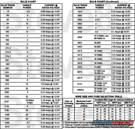
c) For added lamp loads, the "Bulb Chart" will aid in determination of common lamp current draws.
4. If the total electrical load on the circuit (after the addition of electrical equipment) s less than 80% of the fuse or circuit breaker protection rating in that circuit and less than the capacity of each limiting component (switch, relay, etc.), the items to be added can be connected directly to that circuit. For fuses located in the engine compartment, the electrical load should not exceed 60% of the fuse or circuit breaker protection rating.
5. If the total electrical load to be imposed on a circuit exceeds the value of the circuit protection, or the value of any limiting component, the items cannot be added directly to the circuit.
a) Added devices exceeding the current capabilities of the factory-installed system are best controlled through the use of a relay or hang-on switch. The coil of the relay (in accordance with the preceding limitations) can be fed from the factory circuit (now acting as a signal circuit) with added wiring providing feeds to the added electrical devices. (Relay selection is important and depends on: current requirements; number of cycles expected in the relay lifetime; whether the relay is to be operated intermittently or for long periods of time, and; whether the relay is exposed to weather conditions or is installed in a protected area. When the current requirements of a circuit exceed the capacity of an available relay, more than one relay can be used if the circuit is wired to split the load).
b) Added wire feeds to the switch or relay power contacts should not be tapped into the basic vehicle wiring. Draw and return power as close to the battery as possible (i.e., the starter motor relay, the engine block or frame, etc.).
c) Circuit protection (fuses or circuit breakers) must be provided for all added wiring. The protection device rating should not exceed the current requirements for the add-on components and should be installed as close to the point of tapped power as possible.
d) Never use the stud on the underhood fuse panel as a junction point.
Wire Gage:
1. When adding wiring, the wire gage size should be determined as follows:
a) Where wire is spliced to extend a circuit, the added wire should have a gauge equal to or lower (larger) that of the circuit being lengthened.
b) Where wire is being added to feed add-on devices, the wire gauge table should be used. (Note: Current capacity of a given wire varies with temperature and type of insulation. The table, however, represents generally accepted values as a guide).
2. Wherever possible, added wiring should have a thermosetting insulation (such as Hypalon or cross-linked polyethelyne/XLPE/PEX) meeting SAE specifications J1128 type SXL, GXL or TXL (SAE specifications J1127 type SGX or STX for battery cables).
WIRE GAGE MAXIMUM CURRENT CAPACITY
(PLASTIC INSULATED COPPER WIRE)
20ga - 10 Amps
18ga - 15 Amps
16ga - 20 Amps
14ga - 25 Amps
12ga - 30 Amps
10ga - 45 Amps
BULB CHART
BULB TRADE NUMBER CANDLE POWER CURRENT @ RATED VOLTAGE
90 6 .58 Amps
94 15 1.04 Amps
67/97 4 .69 Amps
97 N.A. .69 Amps
105 12 1.00 Amps
161 1 .19 Amps
168 3 .35 Amps
192 3 0.33 A @ 13.0V
194 2 .27 Amps
211-2 12 .97 Amps
212-2 6 .74 Amps
214-2 4 .50 Amps
561 12 .97 Amps
562 6 .74 Amps
573 32 2.00 Amps
578 9 0.78 A @ 12.8V
579 9 0.8 A @ 12.8V
631 6 .63 Amps
904 4 0.69 A @ 13.5V
904NA 5.3 0.69 A @ 13.5V
906 6 0.69 A @ 13.5V
912 12 1.0 A @ 12.8V
916 2 0.54 A @ 13.5V
916NA 1.5 0.54 A @ 13.5V
921 21 1.4 A @ 12.8V
922 15 0.98 A @ 12.8V
1076 32 1.80 Amps
1156 32 2.10 Amps
1157 (OR or N.A.) 32 /3 2.10/.59 Amps
1157A (major) 24 2.1 A @ 12.8V
1157A (minor) 2.2 0.59 A @ 14.0V
1178 4 .69 Amps
1195 50 3.00 Amps
1196 50 3.00 Amps
1445 .7 .14 Amps
1815 1.4 .20 Amps
1816 3 .33 Amps
1891 2 .24 Amps
1892 .75 .12 Amps
1893 2 .33 Amps
1895 2 .27 Amps
3057 (major) 32 2.1 A@ 12.8V
3057 (minor) 32 2.1 A @ 12.8V
3057K (major) 32 2.1 A @ 12.8V
3057K (minor) 2 0.48 A @ 14.0V
3155K 21 1.6 A @ 12.8V
3156 (P27W) 32 2.1 A @ 12.8V
3157 (P27/2W) (major) 32 2.1 A @ 12.8V
3157 (P27/2W) (minor) 3 0.59 A @ 14.0V
3157A (major) 24 2.1 A @ 12.8V
3157A (minor) 2.2 0.59 A @ 14.0V
3157K (major) 32 2.1 A @ 12.8V
3157K (minor) 3 0.59 A @ 14.0V
3456K 40 2.23 A @ 12.8V
3457AK (major) 30 2.23 A @ 12.8V
3457AK (minor) 2.2 0.59 A @ 14.0V
3457K (major) 40 2.23 A @ 12.8V
3457K (minor) 3 0.59 A @ 14.0V
3757AK (major) 24 2.1 A @ 12.8V
3757AK (minor) 2.2 0.59 A @ 14.0V
4000 37.5, 60 Watts 3.14, 5.04 Amps
4001 26,000 3.14 Amps
4002 21,000 Low 14,000 Hi 4.20, 3.14 Amps
4057K (major) 32 2.23 A @ 12.8V
4057K (minor) 2 0.48 A @ 14.0V
4157K (major) 32 2.23 A @ 12.8V
4157K (minor) 3 0.59 A @ 14.0V
4405 50,000 2.58 Amps
4412 35 Watts 2.74 Amps
4414 18 Watts 1.41 Amps
H6054 35, 65 Watts 2.94, 5.46 Amps
4415 35 Watts 2.73 Amps
4416 30 Watts 2.34 Amps
4435 75,000 2.34 Amps
4475 30 Watts 2.34 Amps
6015 27,500 Low 30,000 Hi 4.10, 4.97 Amps
6014 27,500 Low 30,000 Hi 4.20, 4.97 Amps
6112 40, 50 Watts 3.10, 3.91 Amps
9003 (HB2) (low) 76 55W @ 12.0V
9003 (HB2) (high) 125 60W @ 12.0V
9005 (HB3) 135 65W @ 12.8V
9006 (HB4) 80 55W @ 12.8V
9007 (HB5) (low) 80 55W @ 12.8V
9007 (HB5) (high) 107 65W @ 12.8V
9008 (H13) (low) - 55W @ 12.8V
9008 (H13) (high) - 65W @ 12.8V
9140 48 40W @ 12.8V
9145 (H10) 65 45W @ 12.8V
W5W 4 0.4 A @ 12.0V
H1 117 55W @ 12.0V
H2 143 4.17 Amps
H3 121 55W @ 12.0V
H7 125 55W @ 12.0V
H9 167 65W @ 12.0V
H11 107 55W @ 12.8V
H6054 (low) - 55W @ 12.8V
H6054 (high) - 65W @ 12.8V
ADDING LIGHTS OR ELECTRICAL DEVICES
Although there are many points in the truck electrical system to connect additional circuits, certain connection points are recommended for reliability and convenience. This section defines the recommended connection points for each Ford truck model and the maximum electrical loads allowable. Alternative connections or wiring practices are not recommended as certain modifications may result in other circuits becoming non-functional. Disconnect the battery negative (ground) cable and remove it from the battery carrier prior to any vehicle modification. Upon completion of body or equipment installation, all wiring should be checked for proper routing, etc. to preclude electrical shorts upon reinstallation of the battery negative cable.
CAUTION: Improper electrical tie-ins may affect vehicle operation (i.e., engine, transmission).
1. LIGHTS CONTROLLED BY HEADLAMP SWITCH
The headlamp switches on all Ford Light Trucks (F-150-350, Bronco, Econoline) employ one integral 15-amp circuit breaker for the headlight circuit, and one 15-amp fuse located in the fuse panel for auxiliary circuits. Connections to any point in the circuits controlled by the headlamp switch should be on the auxiliary fuse. Connections to the #12 circuit (headlamp hi-beam, green wire/black stripe), the # 13 circuit (headlamp low-beam, red wire/black stripe) and the #15 circuit (feed wire to dimmer switch, red wire/yellow stripe) should be avoided. If the total load on the headlamp circuit breaker exceeds the breaker rating, the headlamps will cycle on and off indicating the overload. If this occurs, a portion of the added lights must be wired through a relay, feeding the relay coil from the headlamp switch. On models equipped with marker lamp switches it is highly recommended added lights employ that circuitry.
F-150 THRU F-350 AND BRONCO
The feed for added lights to be controlled by the headlamp switch should be terminated in a female connector and be connected to the male take-out (brown wire #14 circuit) on the left-hand side of the instrument panel harness (near the emergency brake). If the vehicle has roof marker lights with dual battery option, this connector will be occupied. In the case of dual battery option, an additional connector (control by the relay) will be provided. In this case, fabricate a " Y" jumper to permit both connections to the single connector. Rear lights to be controlled by the headlight switch can be spliced into the #14 circuit (brown wire) at any point in the taillamp harness. NOTE: On trailer tow and camper option, a plug connector is provided at the left-hand rear frame to which taillamp connection can be made.
ECONOLINE
REAR LIGHTS: Splice into #285 circuit (brown) in cross-over harness at rear of truck.
FRONT LIGHTS: Splice into #285 circuit (brown) in 14401 wire asembly along right or left fender apron.
LATE-MODEL F-SUPER-DUTY
The head lamp switch used on the Super Duty F-Series vehicles is a low current switch designed to signal the SPDJB to activate all exterior lighting. The left- and righthand low beam lamps are then fused individually using a 10A fuse located in the SPDJB fuse box. The high beam lamps are fused using a separate 15A fuse while the interior lamps are fused using 10A fuses located in the SPDJB fuse box. A connection to any circuit in the system controlled by the head lamp switch must be done using an auxiliary relay. Any connection must be performed on the lighting output of the SPDJB additional load connected to the headlamp switch will damage the headlamp switch. A marker lamp relay circuit 962 for SUB additions is provided for convenience as standard equipment on chassis cabs, optional on pickups. Do not connect to other OEM wires. Adding additional loads to headlamp circuits may require SPDJB to be reconfigured for snowplow - TSB-7-9-1
2. ADDED LIGHTS CONTROLLED BY ROOF MARKER LAMP SWITCH
F-150 THRU F-350 - ALL MODELS: Not applicable - no roof marker lamp switch is installed. Roof marker lamps are controlled directly by the headlamp switch (except on camper, stake and platform models and /or dual battery option, whose marker lamps are controlled by an 18-amp relay which is operated by the headlamp switch).
ECONOLINE: Not applicable - No roof marker lamps are installed.
3. LIGHTS CONTROLLED BY STOP LAMP SWITCH AND TURN INDICATOR SWITCH
Two types of stop lamp switches are in use on Ford trucks: mechanical switch operated by brake pedal, and an air switch operated by air pressure in the brake system. These switches are designed for maximum loads usually less than the fuse or circuit breaker in the circuit but ample for normal stop lamp loads. These maximum loads are: 8 amps for air operated switches and 12.5 amps for mechanical switches (2004-up 15A). Under no circumstances are total loads in excess of these values permissible. All Ford light trucks are released with a mechanical stop lamp switch mounted on the brake pedal arm for Econoline, and on the pedal pin and master cylinder push rod for F-Series & Bronco. This switch has a maximum allowable electrical load of 12.5 amps.
a) If only stop lamp function is desired for the added lights, splice into the #810 circuit, red wire/black stripe for Econoline (#10 circuit, light green-red hash marks for F-Series) between the stop lamp switch and the turn indicator switch (2004-up YE-GN CLS43 at the blunt cut customer access wire located at the rear of the vehicle near trailer tow connector C4099).
b) If only turn signal function is desired for the added lights, connect right-hand lights to circuit #2 (white wire/blue stripe) and lefthanded lights to circuit #3 (green wire/white stripe). This connection can be made by splicing into the wires near the parking lights or near the steering column. (See note below).
c) If both turn signal and stop lamp function are desired for the added lights, splice into the taillamp loom, using circuit #282, green wire for Econoline (circuit #5, orange-light blue stripe for F-Series) for right-hand lights and circuit #283, yellow wire/black stripe for Econoline (circuit #9, light green-orange stripe for F-Series) for left-hand lights. (See note below.)
NOTE:
1. The early turn signal switch used on light trucks has a maximum rated current of 6.5 amps for right and left turning functions and 8.0 amps for stop lamp function. Do not exceed these values on the turn signals. The 2004-up turn signal switch is designed to use a low current to signal the SPDJB to activate turn signal and stop lamps. The switch is not designed to directly power any lamps or other electrical devices.
2. The turn signal and emergency flasher system on early light trucks utilizes two flashers, one for emergency flasher function. These flashers are designed to accommodate a two-light (4.2 amps) load for the turn signal flasher and a six-light load (12.6 amps) for the emergency flasher. If one additional 2.1-amp light is added to each side (total 6 lamps)the C8AB-13350-A turn signal flasher must be replaced with a C6AB-13350-B flasher. The addition of two 2.1-amp lamps to each side (total 8 lamps) will require replacing the existing two flashers with a single C8TB-13350-A transistorized flasher and, because of the complexity, is not recommended. The addition of lights without a flasher revision will result in a very fast, unacceptable flashing rate.
3. Do not splice into turn/stop circuits at SPDJB, or into turn circuits at multi-function switch. Splicing in those areas will damage the switch or cause the SPDJB to malfunction. Use the trailer tow circuits and trailer tow relays to power added turn/stop lights. Circuits are accessible at the rear of the vehicle LT/Stop=YE, RT/Stop=GN. Reverse/back-up lights must be tied-in using trailer tow relays and circuits in same manner as turn/stop lights.
4. Splicing into the stop lamp switch on vehicles with Electronically Controlled Transmissions can interfere with the proper functioning of PCM, speed control, and anti-lock brake electronic modules. This can:
- Affect EFI engine idle speed quality.
- Prevent the Powertrain Control Module torque converter clutch from applying at throttle openings less than half throttle.
- Deactivate anti-lock brake system operation
- Prevent the speed control from disengaging upon braking.
4. ADDED LIGHTS OR ACCESSORIES CONTROLLED BY ADDED SWITCHES
This section describes the connection points for added electrical accessories when these accessories are to be controlled by added switches not a part of the Ford-released vehicle. The added switches and wiring must have sufficient electrical capacity for the accessory load and must be protected by appropriate fuses or circuit breakers. Additional loads on Ford-provided fuses may cause nuisance fuse blows. Also, added current draw must not cause total loads to exceed capabilities of the base vehicle wiring.
For added electrical accessories that operate only when the ignition is on - terminate the feed wire from the hang-on switch in a bullet connector and plug into the three-way accessory plug (yellow) on the instrument panel harness (single black wire/green stripe). This circuit is protected and needs no additional fusing.
5. RADIO FREQUENCY INTERFERENCE (RFI)
During modifications to the vehicle, manufacturers should take the necessary precautions to maintain the RFI integrity of components. (Canada has an RFI regulation in effect, see page 226.) Precautionary procedures and components listed below are examples and do not necessarily represent a complete list.
a) All components required to suppress RFI emissions, which are removed during service, repair, or completion of the vehicle, must be reinstalled in the manner in which they were installed by Ford.
b) Shields on distributor and ignition coil use capacitors as required.
c) Replacement spark plugs, ignition wires, ignition coils, distributor caps and distributor rotor must be equivalent in their RFI suppression properties to original equipment.
d) Electrical grounds on all components must be retained.
e) Metallic components installed on the body or chassis must be grounded to the chassis.
f) Electrical circuits added to the vehicle should not be installed near the high tension ignition components.
g) Only " static conductive" accessory drive belts should be used.
h) Fan, water pump, power steering and other belts should be of the OEM type or equivalent that will not build up a static electrical charge.
i) For any completed vehicle, additional measures may be needed to adequately suppress RFI emissions.
j) Guidance for installing two-way mobile radios can be found via the web at
http://www.fordemc.com/docs/download/Mobile_Radio_Guide.pdf .
6. GUIDELINES FOR POWERTRAIN CONTROL SYSTEM APPLICATIONS:
All Powertrain Control Module wiring, in particular the 12A581 and 14401, must be a minimum of 2 inches from secondary ignition coil wires and at least 4 inches from the distributor, ignition coil tower, and starter motor (and its wiring) as well as 4 inches from the alternator output wiring. These clearances apply in particular to all PCM sensor and actuator pigtail wiring. PCM wires shall not be in the same bundle as other high-current non-PCM circuits (e.g., tachometer wire from coil to Thick Film Ignition Module (TFI), power seat/door lock/window, horn, alternator reg.) for a distance of more than 20 inches.
7. CHECK ENGINE WARNING LIGHT:
The check engine warning light is a device required on certain vehicles to indicate malfunctions of the Powertrain Control Module. For all vehicles except ESeries Super Duty Stripped Chassis (which is not equipped with a dashboard), if a warning light is required, it is Ford installed and operational. The light is also required for all gasoline powered E-Series Super Duty Stripped Chassis vehicles. The warning lamp is included in the supplied instrument cluster, located in the dunnage box. It should be recognized that this light is a requirement of Emission Certification. If an alternate instrument cluster is utilized, the final stage manufacturer must install an operational light in the dashboard. This light must glow amber and display the message, "SERVICE ENGINE SOON." Once the light has been completed by the final stage manufacturer, proper function can be determined by turning the key to the on position. The light should come on prior to engine cranking and go out when the engine starts. If the light does not come on as above, refer to Section 14 (Quick test step 7 - Diagnostics by Symptom) of Volume H (Engine and Emission Diagnostic Manual) of the Car and Truck Service Manual for diagnostic procedure.
After all electrical or vehicle modifications, perform the on-board diagnostics as described in the powertrain control/emissions diagnosis (PCED) manual to clear all diagnostic trouble codes (DTCs). Road test vehicle and rerun the on-board diagnostics to verify that no DTCs are present.
If DTCs are generated, perform the appropriate diagnostic procedures and repairs. Vehicle operation (engine/transmission) may be affected if DTCs are not serviced.
It is the body builder's responsibility to use sound engineering judgment when making any modifications to a vehicle, and the body builder is responsible for ensuring that all modifications made are appropriate for the intended vehicle application.
NOTE: The final stage manufacturer is responsible for ensuring that the final vehicle configuration meets all applicable regulatory requirements.
___________________________________________________
"Grounding" is commonly misunderstood...
When electricity first became publicly available (when Edison & Tesla were fighting over DC vs. AC), Copper wire was very expensive. So rather than run 2 wires everywhere, Tesla realized he could run a "hot" wire, and then use the ground (the actual dirt of the Earth) as the return circuit path. (He also thought he could use the ionosphere as the hot side, but he never got that to work.) Inside a house, there still had to be 2 wires, but one of them went "to the ground" via a Copper rod driven into the dirt outside the house. That became known as "the ground wire". When vehicles acquired electric circuits (AFAIK, the first on any Ford was the electric horn, which Ford always numbers as circuit #1), it was equally-efficient to use the metal chassis of the vehicle as one of the main electrical pathways, to reduce the amount of wire needed. And the term "ground" was carried over into that arena. Chassis grounding worked reasonably-well until alternators got up into the ~100A range (in the 80s) and vehicle wiring harnesses began to exceed the weight of the drivetrain (AFAIK, the first to cross that line was the '92 Lincoln Continental V6). Since then, more circuits are networked through high-speed data bus lines via communication modules so that you don't need a discrete wire running from one end of the vehicle to the other & another coming back to turn on a taillight, and confirm that the bulb isn't burnt out.
But as a result, the chassis/body ground is no longer sufficient to provide a reliable circuit path without introducing a lot of background noise (RFI) into those minuscule high-frequency data signals. So the trend for a couple of decades now has been to run actual Copper return wires so that far less current flows through the chassis steel. (House wiring standards added a return "neutral" wire decades before that.)
So by definition, if you're using a wire to return to the battery, you're not "grounding" that circuit - you're wiring it. And wiring it is a good idea when you're dealing with rusty 40- to 50-year-old body & frame steel. The catch is that the return wiring has to be AT LEAST as large as ALL the power wiring that it serves - IOW, very big like the alternator output wire, the starter wire, the winch wiring, and the ignition switch battery-supply wires. None of it needs to be bigger than the battery cables because you can't ever get more current flowing than the battery can put out (roughly whatever its CA rating is).
So if you want to be sure you have a good return path throughout any vehicle, just extend the battery (-) cable all the way to the trailer connector. Obviously, you can't run a cable that big into the trailer connector or anything else - you have to splice onto it to branch off with smaller black wire (or whatever color the particular circuit uses for "ground"). That's why I refer to that as a "trunk ground" system - the main return wire is like a big tree trunk, with the variously-sized smaller branches shooting out to hit each point on the vehicle that needs an exceptionally-reliable return (generally: the high-current devices; and those that require low RFI noise, like audio amplifiers).
Fortunately, those splices DON'T need to be insulated - they can be left showing bare metal. Copper & solder don't corrode very quickly in air, or even in common rainwater. Mainly just at the battery where acid leaks out. Road salt will eventually cause some corrosion, but probably not enough to matter within the remaining lifespan of even the best-maintained antiques.
And the body & frame should still be GROUNDED at a few points, just to reduce galvanic corrosion, and to serve the very-low-current chassis-grounded loads like taillights & fuel level senders.
Some vehicles also have large un-insulated woven wire straps joining large metal components, but those are not power grounds. Those are RFI grounds, used to reduce the amount of electromagnetic noise passing through those components.