Annotated collage of heavy-gauge battery cable terminals being s…
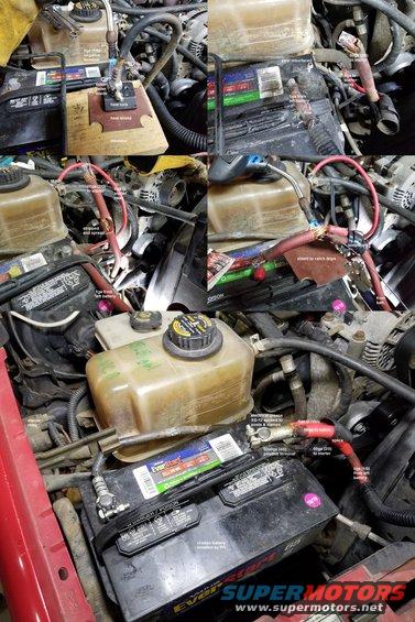
The negative terminal was easy: after cutting the original Lead clamp away, stripping enough cable to go in the new terminal, and brushing off the corrosion, I dropped the solder pellet in and torched the terminal until the cable dropped in, pushing out some of the liquid solder. I kept heat on it for a few more seconds to make sure the cable got hot enough to wick some solder up, and then sprayed it with clean water.
IF THE IMAGE IS TOO SMALL, click it.
The positive was MUCH more work... Since the other battery was still connected, and I added a jumper cable to power the KAM & radio memory, only the big starter cable was dead - the other 2 were still live ( 12VDC) and dangerous. But I prevented either from grounding during the process.
I couldn't buy a terminal large enough to accept all 3 cables, so I spliced the 2 big ones first, then soldered the largest & smallest into the 0000ga (4/0) positive terminal. Because torching wires directly isn't a reliable way to solder them, I added a sleeve of 3/4" hard (thin-wall) Copper tubing, and then two Copper crimp rings (for PEX fittings). Red heat-shrink tubing covers all that, and some of the charred original insulation. Of course, all 4 posts, terminals, bolts, & nuts got a light coat of electrical grease just before re-connecting them to the posts.
Cleaning down to shiny metal is good maintenance for ANY exposed connection like the battery terminals & most ground ring terminals, or high-current case-grounded device (like a starter or alternator mount). .
.  .
.  .
.  .
. 
Electrical Grease XG-12 (F8AZ-19G208-AA)
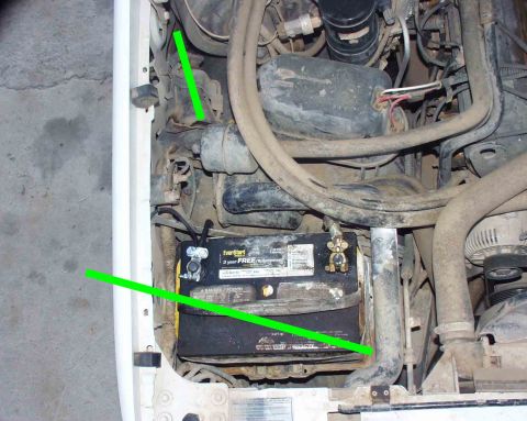
To bypass the voltage regulator and force the alternator to its peak output (at the current RPM), BRIEFLY ground the indicated or capped screw on the voltage regulator (back of the alternator). If the output does NOT spike, the alternator is probably bad. Don't keep it grounded any longer than it takes to get a voltage or current reading because the alt will overheat rapidly, especially at hi rev, and any electrical components (including the battery) can be damaged. .
.  .
. 
DO NOT USE Silicone Brake Caliper Grease And Dielectric Compound XG-3A (D7AZ-19A331-A) on electrical connections or terminals.
Is this accurate? Sign in to help verify it.
Comments
More from this build


No comments yet.