Ford TSB 90-25-12 vacuum cruise control voltage and resistance t…
TSB 90-25-12 Vacuum Cruise System Diagnosis (pre-'93 F-series & Bronco)
IF THE IMAGE IS TOO SMALL, click it.
See also: .
.  .
.  .
.  .
.  .
.  .
.  .
.  .
.  .
.  .
. 
ISSUE: Integrated Vehicle Speed Control (IVSC) was introduced on some 1986 units. The IVSC system uses the EEC IV processor as the control module. Before IVSC a Stand Alone Speed Control System was used on all applications. The Stand Alone Speed Control System uses a separate control amplifier.
ACTION: Refer to the following diagnostic information when servicing speed control concerns. Refer to the Speed Control System Application chart to determine which type of system is used for a specific model.
NOTE: THE DIAGNOSTIC INFORMATION ON THE FOLLOWING PAGES WILL APPLY TO THE STAND ALONE AND INTEGRATED VEHICLE SPEED CONTROL SYSTEMS UNLESS A SPECIFIC VEHICLE TYPE IS REFERENCED.
"TRICKS OF THE TRADE"
Many speed control concerns can be easily resolved by using the following "Tricks of the Trade" diagnostics. If a concern cannot be resolved, refer to the shop manual, Section 37-05 for additional component testing.
VERIFY CUSTOMER CONCERN
Before performing speed control diagnosis, the customer concern should be verfied. Occasionally, the customer does not completely understand operation of the speed control system. If this is the case, the customer should be referred to the Owner Guide for complete speed control operating instructions.
Most misunderstanding involves operation of the RESUME feature. RESUME should be used to return to a previously set speed after speed control operation has been interrupted. The RESUME feature will not operate if the vehicle speed has been lowered through use of the COAST button. The release of the COAST button sets the new lower speed into the control memory. Also, RESUME will not work if the vehicle speed is below the minimum speed control operating speed of about 30 mph (48 km/h).
The RESUME function for the Stand-Alone Speed Control System may not activate with a momentary tap of the RESUME button. The RESUME button must be held down for a short time to ensure engagement.
Speed drops of more than 1 or 2 mph may occur while in speed control operation on grades or under other load conditions. This is especially true on vehicles that are equipped with automatic overdrive transmissions or with manual 5 speed transmissions. These speed drops are due to limited engine power available in the overdrive (or the highest gear of a manual transmission) mode of operation. Under heavy load conditions, such as hilly or mountainous areas or during trailer tow, the vehicle speed may drop even more. When speed drops of 10 - 13 mph (16 - 21 km/h) occur, the speed control system will, by design, automatically disengage.
SYSTEMS
The speed control system obtains vehicle speed information from the vehicle speed sensor. In most cars and trucks the sensor is mounted on the transmission or in-line with the speedometer cable. The sensor is driven from gearing in the transmission. On 1986-90 Lincoln Town Car, Crown Victoria, Grand Marquis and Mark VII vehicles the speed signal comes from a speed sensor located in the Electronic Instrument Cluster. If the speedometer system is erratic or inoperative, it must be serviced before the speed control system is evaluated.
The speed control system also interacts with the brake system, and with the clutch system on manual transmission vehicles. Speed control requires electrical continuity through the stoplamps (and clutch switch on manual transmission vehicles) in order to operate. Proper stoplamp operation is required if the system is to disengage with brakes. Proper clutch switch operation is also required on manual transmission vehicles if the system is to disengage with clutch pedal actuation. Stoplamp and clutch switch circuit diagnosis is detailed in Section 37-05 of the appropriate Shop Manual.
NOTE: SPEED CONTROL WILL NOT DISENGAGE IF THE GEARS ARE SHIFTED ON A MANUAL TRANSMISSION VEHICLE WITHOUT DEPRESSING THE CLUTCH PEDAL.
VISUAL INSPECTION
Visual inspection is an important part of diagnosis. The visual inspection should be done to locate obvious reason for the customer concern.
When performing visual inspection, check all items for abnormal conditions. Look for items such as bare, broken or disconnected wires and damaged vacuum hoses.
For the speed control to function properly, it is necessary that the speedometer cables, if so equipped, be properly routed and securely attached. All vacuum hoses must be securely attached and routed with no sharp bends or kinks. The servo (throttle actuator) and throttle linkage should operate freely and smoothly.
Any concerns found by the visual inspection should be corrected before further tests of the speed control system are made. The following items should be inspected.
GENERAL
* Does the horn work? If not, check the horn circuit fuse, horn relay and horn circuit wiring.
* Do the stoplamps light when the brake pedal is depressed? If not, check the stop lamp circuit fuse, stoplamps, wiring and stop lamp switch.
AMPLIFIER
Check for unseated connectors at the speed control amplifier. The amplifier location varies by carline. Refer to the appropriate Shop Manual, Section 37-05, for location.
* Look for loose or unseated connector pins.
* Check for broken wires at the connectors.
SERVO
Check for the following items.
* Disconnected or cut vacuum hose from the servo to the manifold source.
* Loose or disconnected electrical connector, or broken wire.
* Loose, or cracked plastic elbow at the servo.
* Disconnected, or loose, dump valve hose at the servo.
ACTUATOR CABLE
* Misadjusted Bowden cable/bead chain. If misadjustment is suspected due to set speed error or excessive speed drop, the cable or chain should be readjusted.
* Cable loose, or not connected to the engine bracket (screw loose or missing).
DUMP VALVE
* Hose pinched or not connected to the dump valve.
* Dump valve is not fully seated into the retaining clip in the brake pedal support bracket.
* Check the dump valve adjustment. Readjust the dump valve if the yellow plunger is extended more than 1/4" when the brake pedal is not depressed.
VOLTAGE/RESISTANCE TESTS
If a concern cannot be found with a visual inspection, it can usually be found with an inspection. It can usually be isolated by making voltage and resistance measurements at the amplifier connectors (Stand-Alone System) or at the EEC-IV connector (Integrated System). The connectors must be unplugged for the resistance checks.
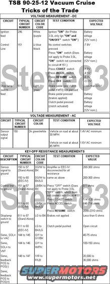
The following tables summarize the circuits and wire color codes used for the speed control system. The proper voltage/resistance readings at the amplifier or EEC-IV connectors are also given. Typical circuit numbers apply to both car and truck applications. Refer to the appropriate Shop Manuals, Section 37-05, or to the Electrical/Vacuum Trouble-Shooting Manuals for the exact circuit number or color code.
VOLTAGE MEASUREMENTS
Connect the negative lead of the voltmeter to circuit 57 (ground) of the Stand Alone Amplifier 6 way connector, or to Pin 40 or 60 of the EEC-IV connector (EEC power ground). Measure the DC or AC voltage with the positive lead of the voltmeter.
RESISTANCE MEASUREMENTS
Connect an ohmmeter between the designated circuits and make the resistance measurements with the ignition "OFF"
ABNORMAL OPERATION DURING "ACCEL" OR "COAST"
In 1986-88 models, the vehicle may exhibit hesitation while using the COAST mode, or hesitation and dropout while using the ACCELmode. This abnormal operation is caused by poor contact between the speed control brushes and the slip rings on the steering wheel. This poor contact is due to a buildup of contamination of the lubricating grease. The condition occurs more frequently when the temperature is hot and on vehicles with high mileage.
Correct the concern by removing the steering wheel and thoroughly cleaning the grease from the brushes and slip rings. Regrease using grease (E8AZ-19590-A). This new grease has been used in production since the beginning of the 1989 Model Year. Its use has resulted in a 90% reduction in the incidence of this concern.
SPEED CONTROL PERFORMANCE - AOD, AXOD AND MTX5
As noted in the Owner's Guide, it may be preferable to shift the AOD or AXOD to the "D" (overdrive lockout) or the MTX5 to 4th gear in mountainous areas or at high altitude to improve speed control performance.
On steep upgrades the vehicle may not be able to maintain speed while in overdrive, or 5th gear, resulting in a speed drop below the set speed. If the speed drop exceeds approximately 10-13 MPH, the speed control will automatically disengage and must be reset with the SET/ACCEL button. Performance will be improved by shifting to "D" (AOD or AXOD) or to 4th (MTX5).
If speed control performance is poor on moderate grades, the adjustment of the Bowden cable/bead chain should be checked and readjusted if necessary. The automatic transmission shift linkage should also be checked for proper adjustment.
STAND ALONE SPEED CONTROL VOLTAGE/RESISTANCE TEST CONNECTIONS
Locate Circuit 203 (orange/light blue). It is used ONLY on the 1991 Lincoln Town Car with electronic cluster. This circuit connects the speed control amplifier to a speed control "set" indicator which is located at the lower edge of the electronic cluster center section. The voltage at circuit 203 is normally 5.0V (speed control not set) and less than 1.0V when the speed control is set. Grounding circuit 203 pin will light the cluster display. The SPEED CONTROL display will light only when a set speed is being maintained and when using ACCEL or RESUME. The display will turn off when braking, using OFF or COAST, with the ignition off.
SPECIFIC CARLINE SYMPTOMS AND CORRECTIVE ACTIONS
If a particular condition is found during any of the visual checks, it should be corrected and the system performance re-evaluated.
OTHER APPLICABLE ARTICLES: 80-25-09
--------------------------------------------------------------------------------
TSB 87-18-19 Cruise Control Vacuum Reservoir
Customer Interest - LOSS OF SPEED GOING UP GRADES - 4.9L OR 5.0L ENGINE WITH AOD TRANSMISSION
LIGHT TRUCK: 1983-87 E SERIES, F SERIES, BRONCO
ISSUE: Loss of speed when going up grades with the speed control engaged and the transmission in overdrive "(D)" may be caused by an insufficient vacuum reserve. Speed loss greater than 10 MPH (16 km/h) will cause the speed control to shut off.
ACTION: To correct this, install a speed control vacuum reservoir using the following service procedure.
1. Remove any slack from speed control actuator cable. Make sure the cable allows the throttle lever to return to idle.
2. Install the speed control vacuum reservoir (E3TZ-9E799-B) as follows:
a. Locate the 5/16" vacuum hose connecting the engine vacuum to the speed control servo.
b. Disconnect the hose at the speed control servo and connect it to the vacuum reservoir port marked "VAC".
c. Route 5/16" vacuum hose from the unmarked port on the vacuum reservoir to the open speed control servo port.
d. Secure the speed control vacuum reservoir.
NOTE: Advise the owner to shift the gear selector to Drive "D" when the vehicle is under a load condition. This information is contained in the Owner Guide.
PART NUMBER: E3TZ-9E799-B
PART NAME: Speed Control Vacuum Reservoir
CLASS: B
OTHER APPLICABLE ARTICLES: None
WARRANTY STATUS: Eligible Under Basic Warranty Coverage
OPERATION: SP871819A
TIME: 0.3 Hr. DLR. CODING: Basic Part No. 9C735 - Code: 53
For other TSBs, check here.
--------------------------------------------------------------------------------
TSB 89-02-07 Speedometer Accuracy
Publication Date: JANUARY 25, 1989
FORD: 1989 and prior ALL CAR LINES
LINCOLN-MERCURY: 1989 and prior ALL CAR LINES
LIGHT TRUCK: 1989 and prior ALL TRUCK LINES
MEDIUM/HEAVY TRUCK: 1989 and prior ALL MEDIUM/HEAVY TRUCK LINES
ISSUE: The accuracy of speedometer/odometer readings may be influenced by several vehicle components or systems. The information in this TSB article is intended to assist technicians in speedometer/odometer concern diagnosis.
ACTION: Use the following supplemental information to assist in speedometer/odometer diagnostics.
OPERATION: A mechanical analog speedometer displays vehicle speed and the odometer displays total distance traveled. The speedometer/odometer assembly is cable driven by either a transmission or a transaxle. All speedometer/odometer assemblies, except for police vehicles are the same with respect to the speed accuracy tolerance used during calibration. The odometer gear ratio is fixed so that all are identical and have no error in the speedometer head.
Electronic digital operation is similar. It could use a drive cable or a speed sensor to drive the speedometer/odometer. An electronic signal is sent from a speed sensor to the digital speedometer/odometer assembly. The speed sensor is driven by a transmission or a transaxle, similar to a cable.
Several areas of concern that may affect speedometer/odometer readings are tires, axle gear ratio and speedometer/odometer drive and driven gears.
TIRES: Improper tire rolling radius and inflation pressure, temperature and size may contribute to inaccurate system readings. System accuracy testing should be performed after the tires are set at the correct pressure as shown on the safety compliance certification label. The tire should be warmed for a short period. Best results are obtained on smooth, dry pavement while driving at a constant speed within the posted speed limit.
AXLE/TRANSAXLE RATIO: The gear ratio of the rear axle or the final drive ratio of the transaxle must be known to select or check if the proper speedometer/odometer drive and driven gears are present. Various gear ratios are available, but usually are not a concern when dealing with speedometer/odometer concerns unless the gear ratio has been changed.
WARNING: NEVER CORRECT SPEEDOMETER READINGS BY CHANGING GEARS UNLESS THE ODOMETER IS ALSO OFF.
DRIVE/DRIVEN GEARS: The speedometer/odometer drive gear is located inside the transmission, transaxle or transfer case and is not easily accessed for change. The driven gear rotates the speedometer cable. Rear wheel drive vehicles have several driven gears with various numbers of teeth available to correct input to the speedometer/odometer head. Front wheel drive vehicles generally do not offer different gears for correction.
GENERAL DESCRIPTION: The maximum allowable odometer system accuracy error is %uFFFD 3.75% of the actual distance traveled. Ford Motor vehicles are well within those limits.
The speed indication is biased high, except on police vehicles with certified calibration speedometers/odometers. As a general rule, the indicated speed is equal to or greater than the actual speed. This is intended to protect the consumer against violating speed laws. Most customer concerns are related to speedometers reading too high at true speeds between 50 MPH and 65 MPH (80 - 105 Km/h). At that speed range, the worst case errors may indicate a speed that is 10% greater than true speed.
The speedometer head is an instrument which processes information sent to it by the rotating speedometer cable. If the system components send the wrong number of revolution per mile to the speedometer head, an inaccurate speed reading and amount of distanced traveled will be displayed. Since there is no error in the fixed gear ratio of the speedometer head odometer, start by checking the accuracy of the odometer even if the customer concern indicates a speed accuracy problem. Odometer accuracy can be checked by using roads established at mile increments or a known local course. If roads with mile markers are used, a five mile stretch is recommended to allow for inaccuracies. If an error is greater than 3.75%, a change to the transmission drive/driven gear selection, tire size, or tire inflation may need attention. The odometer should be checked again to verify any corrective action. If the indicated speed error exceeds 10% between 50 MPH and 60 MPH (80 - 105 Km/h), replace the speedometer/odometer assembly. Vehicles with transfer cases that have fluctuating readings may be due to slippage of drive gears, parts not splined or loose yoke nuts.
If the vehicle has speed control, the speed accuracy can be checked using the verified odometer vs. time. The formula is as follows:
3600 divded by TIME (seconds to cover one mile) = TRUE MPH(Km/h)
EXAMPLES:
60 MPH (96 Km/h) requires 60 seconds to cover one mile
55 MPH (88 Km/h) requires 65 and 3/4 seconds to cover one mile
50 MPH (80 Km/h) requires 72 seconds to cover one mile
SUPERSEDES: 84-14-06
WARRANTY STATUS: INFORMATION ONLY
--------------------------------------------------------------------------------
For electronic cruise troubleshooting ('93-04), see this:
Is this accurate? Sign in to help verify it.
Comments
More from this build


No comments yet.