Home/
Registry/
Ford/
Bronco/
1980-1986/
“That dirty old truck”/
Photo
supermotors.net/registry/media/1172136
1992 Ford Vacuum Cruise Control Valve & Hose Install at Brake Pedal Diagram

Reference · 1980-1986 BroncoAll 61 exploded parts diagrams
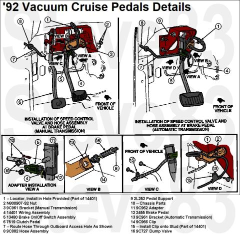






'92 Vacuum Cruise Pedals Details
IF THE IMAGE IS TOO SMALL, click it.
'93-96/7 with electronic cruise similar.
See also: .
.  .
.  .
.  .
.  .
.  .
.  .
.  .
.  .
.  .
.  .
. 
Part of 1980-1986 Ford Bronco Exploded Parts Diagrams
This document, titled "'92 Vacuum Cruise Pedals Details," is an exploded parts and installation diagram showing how the vacuum speed control (cruise control) valve and hose assembly mount at the brake pedal on a 1992 Ford truck/Bronco. Two main illustrations cover installation for manual transmission vehicles (which include the clutch pedal, part 7519) and automatic transmission vehicles, each with numbered callouts and directional "FRONT OF VEHICLE" arrows. Four detail views (Views A-D) show the adapter installation, dump valve and clip arrangement, hose routing at the front of the vehicle, and the bracket area. A 16-item legend identifies components by Ford base part number, including the 14401 wiring assembly, N800907-S2 nut, 9C961 brackets (separate versions for manual and automatic transmissions), 13480 brake on/off switch assembly, 9C802 hose assembly, 2L252 pedal support, 9C962 adapter, 2455 brake pedal, 9C966 clip, and 9C727 dump valve. Installation notes instruct routing the hose through the outboard access hole and installing the clip onto the stud that is part of the 14401 wiring assembly. A reader can learn part identification, the difference between manual and automatic transmission cruise valve brackets, and correct hose/clip routing at the pedal assembly.
Is this accurate? Sign in to help verify it.
Frequently asked questions
- What part number is the cruise control dump valve in this diagram?
- The dump valve is Ford base part number 9C727 (item 16, shown in View B).
- Is the bracket different for manual and automatic transmissions?
- Yes. Item 3 is the 9C961 bracket for manual transmission, and item 13 is a 9C961 bracket for automatic transmission; the diagram shows separate installations for each.
- How should the speed control hose be routed?
- Item 7 instructs to route the hose through the outboard access hole as shown; the hose assembly is part 9C802.
- What is the brake on/off switch part number shown?
- Item 5 identifies the brake on/off switch assembly as part 13480.
- Where does the clip on the wiring assembly install?
- Item 15 instructs to install the clip onto the stud, which is part of the 14401 wiring assembly; item 14 is the 9C966 clip.






No comments yet.