Corroded fuel injector or sensor with red O-ring held in hand
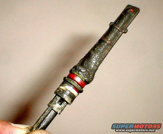
This was after my compressor crapped out. The 2 ears at the top are supposed to keep it from sliding too far into the evaporator inlet. The white end goes in first. The red indicates this orifice is sized for R-134a; a blue orifice is for R-12. .
. 
Because of all the metal shavings that have obviously come out of the failing compressor, the condenser core must be replaced. Most shops don't have the equipment to clean it well enough to ensure NONE goes back around into the new compressor.
For more info, see this: .
.  .
. 
TSB 95-18-04 A/C Flushing
Publication Date: SEPTEMBER 11, 1995
FORD: 1985-86 LTD
1985-88 EXP
1985-94 TEMPO
1985-95 CROWN VICTORIA, ESCORT, MUSTANG, THUNDERBIRD
1986-96 TAURUS
1989-93 FESTIVA
1989-95 PROBE
1994-95 ASPIRE
1995-96 CONTOUR
LINCOLN-MERCURY: 1984-92 MARK VII
1985-86 MARQUIS
1985-87 LYNX
1985-94 TOPAZ
1985-95 COUGAR, GRAND MARQUIS, TOWN CAR
1985-96 CONTINENTAL
1986-96 SABLE
1987-89 TRACER
1991-93 CAPRI
1991-95 TRACER
1993-95 MARK VIII
1995-96 MYSTIQUE
MERKUR: 1985-89 XR4TI
1988-89 SCORPIO
LIGHT TRUCK: 1985-90 BRONCO II
1985-95 BRONCO, ECONOLINE, F-150-350 SERIES
1985-96 RANGER
1986-95 AEROSTAR
1991-96 EXPLORER
1993-95 VILLAGER
1995-96 WINDSTAR
ISSUE: Ford Motor Company has approved a procedure to provide technicians with a non-CFC method of flushing contaminated A/C system heat exchangers (evaporators and condensers). This procedure allows the A/C components to be cleaned and flushed while installed in the vehicle. The types of contamination flushed include particle matter which results from compressor or desiccant failure and the gummy residue which may form when refrigerant oil is overheated. Some Ford authorized HFC-134a retrofit kit procedures will also require A/C system flushing to remove mineral oil for capacity reasons.
ACTION: Refer to the following text for proper flushing procedures.
The flushing procedure is a two-step process which involves the use of an A/C Flusher. The Flusher is used to do the following:
1. Circulate the flushing solvent through the A/C system heat exchangers in the reverse direction of normal refrigerant flow (back flushing). Particle matter is filtered from the returning solvent and the solvent is returned to the reservoir for continued circulation.
2. Remove the flushing solvent from the A/C system. In this step, pressurized air (90-125 psi/620-862 kPa) is used to push and evaporate any remaining flush solvent from the heat exchangers.
Only Rotunda Item No. 014-00990 A/C Flushing Kit which includes 014-00991 A/C Flusher, 014-00992 A/C Flusher Fitting Kit, and F4AZ-19579-A A/C Flushing Solvent (case of 4 gallons/15 L), is approved for use on Ford vehicles. No other flushing device or solvent is approved by Ford Motor Company for flushing A/C systems. The use of other equipment or solvent may cause damage to the A/C system and the flushing unit.
Minimum time for flushing is 15 minutes and minimum time for air flushing is 30 minutes. Failure to continue air purge for the entire 30 minutes as specified may result in residual amounts of flush solvent contaminating the A/C system. Residual flush solvent in a functioning A/C system may lead to A/C system failure.
Do not flush through orifice tubes, TXVs, accumulator/driers, receiver/driers, mufflers or hoses. Internal plumbing and material make-up of these components make it impossible to properly remove the debris and/or residual flushing solvent.
One (1) gallon (3.8 L) of Ford A/C System Flushing Solvent is used in this device and is intended for one (1) vehicle only. It may be used to flush both heat exchangers on an individual vehicle, but under no circumstances should it be used on more than one (1) vehicle. The filter used when flushing is also intended for use on one (1) vehicle only.
NOTE: DURING THE FLUSHING PROCESS, THIS MATERIAL MAY COLLECT RESIDUE FROM THE A/C SYSTEM, WHICH MAY INCLUDE CFC-12. DISPOSE OF THE SOLVENT AND FILTER IN ACCORDANCE WITH FEDERAL, STATE AND LOCAL REGULATIONS.
Use of A/C system filter kits as prescribed in TSB 94-15-5 is optional if the A/C system is flushed. Filter kit use is recommended after flushing if the system is highly contaminated. If the hoses are clogged with debris, hose replacement is required.
Always remember to match oil properly, replace the accumulator/drier and orifice tube, or TXV and receiver/drier when servicing an A/C system with a compressor or desiccant failure.
The following vehicles require A/C system flushing with retrofit kits to remove mineral oil for capacity reasons.
1993 Probe 2.0L and 2.5L
1988-90 Escort 1.9L EFI
1989-93 Thunderbird Super Coupe
1986-92 Mark VII
1991-93 Capri 1.6L and 1.6T
1988-93 Festiva 1.3L
1987-90 Tracer 1.6L
1985-89 XR4Ti
1988-89 Scorpio
OTHER APPLICABLE ARTICLES: 94-15-05
SUPERSEDES: 95-08-01
WARRANTY STATUS: Eligible Under The Provisions Of Bumper To Bumper Warranty Coverage For 1991-95 Lincolns And All Other 1992-95 Models
OPERATION DESCRIPTION TIME
951804A Flush Evaporator 1.0 Hr.
951804B Flush Condenser 1.0 Hr.
For other TSBs, check here.
--------------------------------------------------------------------------------
TSB 91-20-12 A/C Pressure Relief Leak
Publication Date: OCTOBER 2, 1991
LIGHT TRUCK: 1987-91 BRONCO, F-150-350 SERIES
1988-91 F SUPER DUTY, F-47
ISSUE: There may be a loss of A/C refrigerant through the A/C compressor high relief valve during idle and stop-and-go traffic conditions. Eventually, there may be a lack of cooling and oil stains may appear around the A/C compressor high pressure relief valve.
The excessive discharge pressure is caused by the recirculation of higher temperature engine compartment air passing through the condenser during idle and stop-and-go traffic conditions. Normally, cooler ambient air passes through the condenser. Since the refrigerant in the condenser cannot be sufficiently cooled by this high temperature air, excessive head pressures are created causing refrigerant to be vented through the high pressure relief valve.
ACTION: Replace the radiator lower air shield, located between the lower radiator support and the front bumper, with a new radiator lower air deflector ( F1TZ-8327-B ). This new air deflector is larger than the old air shield and will minimize the amount of hot air recirculation through the condenser. Refer to the 1991 Bronco, Econoline, F-Series, F-Super Duty Truck Shop Manual, Section 01-08, for service details.
NOTE: TO REPLACE THE DEFLECTOR ON OLDER VEHICLES, IT WILL BE NECESSARY TO DRILL HOLES, FOLLOWING THE HOLE PATTERN IN THE NEW DEFLECTOR, BEFORE IT CAN BE ATTACHED.
PART NUMBER PART NAME
F1TZ-8327-B Radiator Lower Air Deflector
OTHER APPLICABLE ARTICLES: NONE
SUPERSEDES: 91-14-13
WARRANTY STATUS: Eligible Under Basic Warranty Coverage
OPERATION DESCRIPTION TIME
912012A Install New Air Deflector 0.4 Hr.
--------------------------------------------------------------------------------
TSB 94-19-20 R-134a Charge
Publication Date: SEPTEMBER 21, 1994
LIGHT TRUCK: 1994-95 BRONCO, F-150-350 SERIES, F-47
ISSUE: Ford Climate Control Division has increased the refrigerant charge in the subject vehicles from 2 lbs. 1 oz. to 2 lbs. 6 ozs.
ACTION: When service to the A/C system is required, recharge the A/C system with 2 lbs. 6 oz. of R-134a. Make the necessary corrections to the 1994-95 Service Manuals, pages 12-00-35, 12-03A-58 for 1994 and 12-00-39, 12-03A-56 for 1995.
Obtain an Authorized Modifications Decal and list the date, dealer number, and summary of alterations performed. Select a prominent place adjacent to the Vehicle Emission Control Information Decal suitable for installing the Authorized Modifications Decal. Clean the area, install the decal, and cover it with a clear plastic decal shield.
OTHER APPLICABLE ARTICLES: NONE
WARRANTY STATUS: INFORMATION ONLY
'80-95 F-series & Broncos w/R-134a originally came with 7oz of PAG-46, and '96 trucks had 11oz.
But TSB 97-10-05 says to add 4oz to '94-95s so that all F134a Broncos & F-series take 11oz.
--------------------------------------------------------------------------------
TSB 93-8-13 Replacement A/C Vacuum Reservoir
Publication Date: APRIL 14, 1993
LIGHT TRUCK: 1992-93 BRONCO, F-150-350 SERIES
ISSUE: The vacuum tank for the heater or heater/air conditioning controls is sonically welded to the side of the heater or evaporator case. If a vacuum leak occurs at the vacuum tank, a different vacuum tank can be used to make the repair without removing the old vacuum tank.
ACTION: Install a new service vacuum tank. Refer to the following procedure for service details.
SERVICE PROCEDURE
1. In the engine compartment, detach the vacuum hose from the sonically welded vacuum tank on the heater or evaporator case.
2. Attach the replacement vacuum tank (F3TZ-19D848-A) in a conveniently located spot that can be reached by the vacuum hose. Several areas are available:
a. On the old sonically welded tank, drill an appropriate size hole in the old vacuum tank and use a self-tapping screw to attach the new replacement vacuum tank. The replacement vacuum tank (F3TZ-19D848-A) has slots which will accept the screws.
b. Attach the replacement vacuum tank and put on the vacuum hose.
3. If the old tank mount location is not suitable, locate an existing screw on the blower case and put the replacement vacuum tank (F3TZ-19D484-A) with its slotted bracket in a position over the screw.
a. Make sure of the following points:
* There is room for the tank.
* The vacuum hose will reach it.
* The replacement tank can be attached with that screw.
b. If necessary, rework the slot on the replacement vacuum tank so the screw will fit through it.
c. Attach the replacement vacuum tank and put on the vacuum hose.
4. Verify that the system operates properly.
PART NUMBER PART NAME
F3TZ-19D848-A Vacuum Tank
OTHER APPLICABLE ARTICLES: NONE
WARRANTY STATUS: Eligible Under Bumper To Bumper Warranty Coverage
OPERATION DESCRIPTION TIME
930813A Install Replacement Vacuum Tank 0.3 Hr.
See also:
Is this accurate? Sign in to help verify it.
Comments
More from this build


No comments yet.