Power Lock & Aftermarket RKE Circuit The door lock circuit WITH…
Power Lock & Aftermarket RKE Circuit
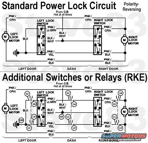
The door lock circuit WITHOUT factory RKE is a common (Ford) polarity-reversing circuit with 2 switches. The switches share the power feed from the battery (always hot). The left (driver's) switch normally holds both motor wires to ground, and the right (passenger's) switch normally holds the motor wires to the left switch wires. When either is operated, it sends one of the wires hot, powering the motors. When operated the other way, the polarity is reversed, reversing the motors' direction. Neither switch is a "master" because neither will work if the other is in the opposite position OR unplugged. Note that the driver's lock motor is NOT connected to the driver's lock switch.
To add relays or switches to the common Ford power lock circuit (like an aftermarket remote keyless entry system), the power (Bk/Wh) is spliced, but the lock & unlock wires must be cut in ONE of the locations indicated by a dashed line. The Bk/Wh wire is not cut.
Uplus = unlock positive
UC = unlock common
Lplus = lock positive
LC = lock common
Obviously, the new ground can be attached to any reliable ground point; not strictly where indicated. But the new power splice should be on the Bk/Wh circuit so it shares the factory circuit breaker, and has constant power.
Any number of switches or relays can be added, but each one must be CUT into the lock & unlock circuits as indicated. And a long series of switches makes for a poor circuit which can be very difficult to diagnose.
Factory RKE (optional '94-up) uses a ground-trigger circuit which can be simply spliced.
Is this accurate? Sign in to help verify it.
Comments
More from this build


No comments yet.