Home/
Registry/
Ford/
Crown Victoria/
1992–1997/
“Vicky (totalled & shredded)”/
Steering Column
supermotors.net/registry/6098/31472
Album section
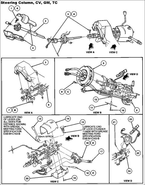
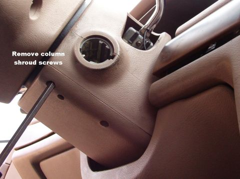
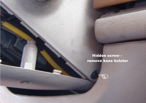
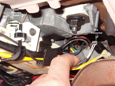
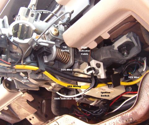
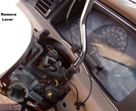
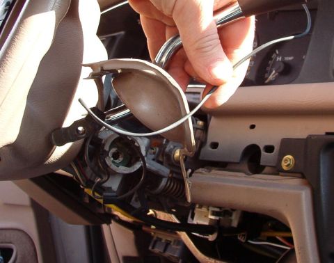
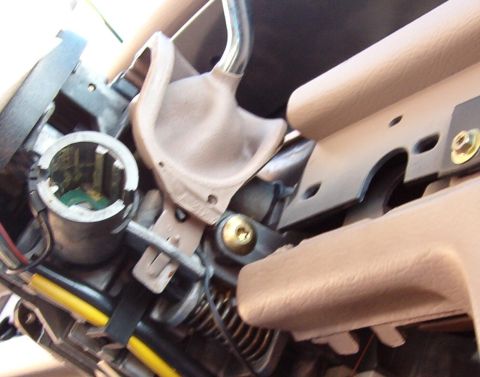
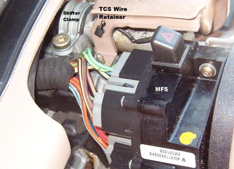
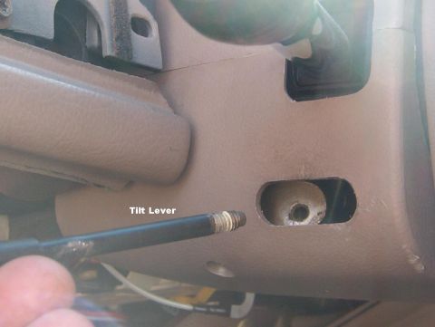
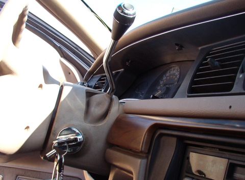
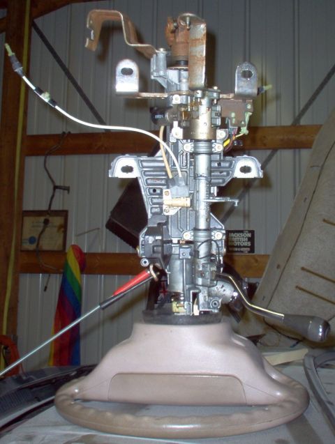
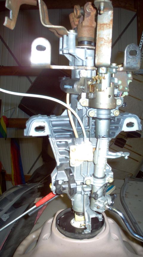
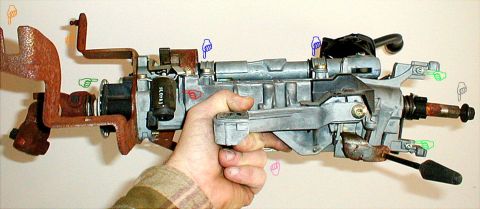
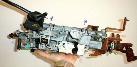
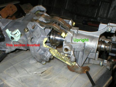
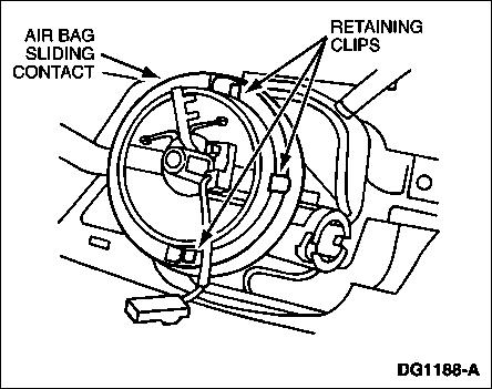
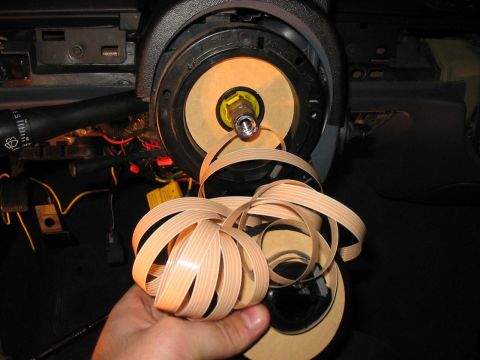
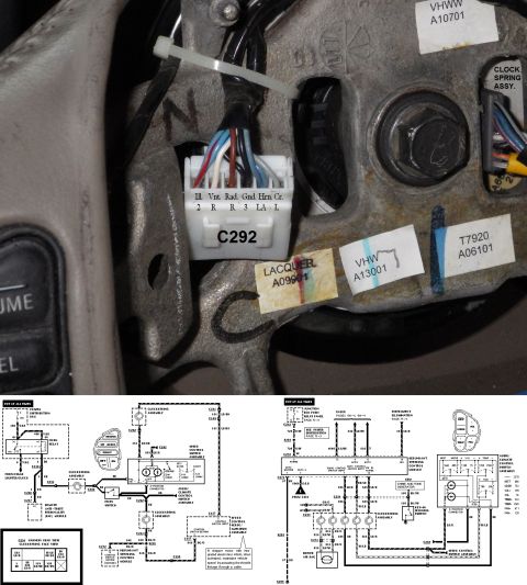
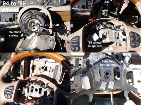
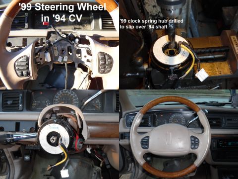
Steering Column
From 1994 Ford Crown Victoria “Vicky (totalled & shredded)” — documented by Steve83.
33 photos
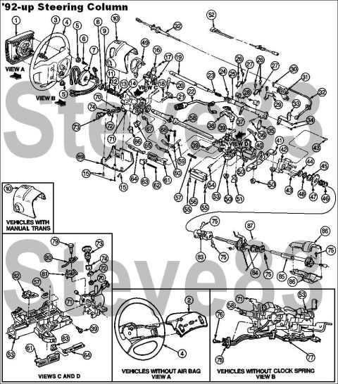
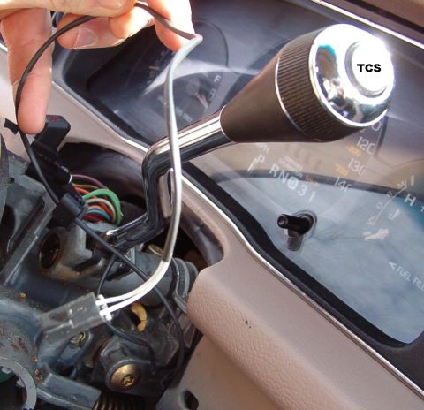
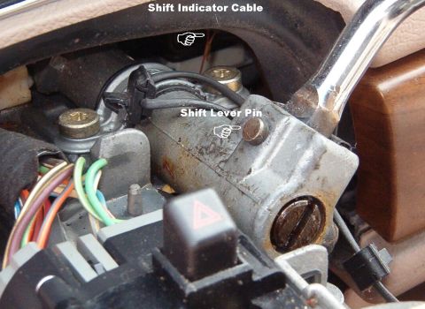
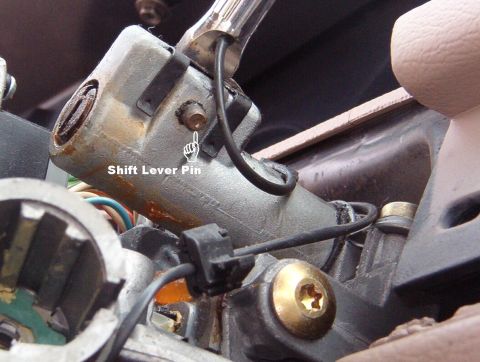
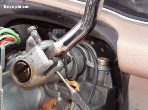
![1994 Ford Crown Victoria - '92-up Steering Column Disassembly See this diagram for a list of all parts. [url=http://www.supermotors.net/registry/media/701936] http://…](https://www.supermotors.net/thumb/573959-480.jpg)