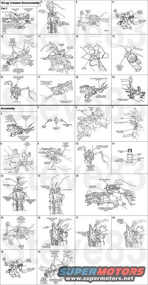
'92-up Steering Column Disassembly
See this diagram for a list of all parts.

1. Disconnect battery ground cable (14301).
2. Remove steering wheel (3600).
3. Remove steering column from vehicle.
4. Remove lower U-joint, spring, sensor ring, and tolerance ring.
5. Remove turn indicator cancel cam (13318 ) by pushing up with flat-bladed screwdriver. Note direction of flush surface.
6. Remove bearing retainer (3C610) and steering column upper bearing spring (3520).
7. Remove steering column bearing sleeve (3518 ) and steering column bearing tolerance ring (3L539).
8. Remove ignition switch (11572).
9. Remove shift lock actuator retaining screws and remove shift lock actuator.
10. Remove transmission column shift selector tube (7212) and transmission shift selector position insert (7A216) (column shift only).
11. Using a drift, tap steering column lock lever pin (3B663) loose. Remove steering column lock lever pin with diagonal pliers. Remove steering column lock pawl (3E691).
12. Remove plastic bearing retainer from lock cylinder housing bore.
13. Remove steering column lock housing bearing (3E700) from lock cylinder housing bore.
14. Remove steering column lock gear (3E717).
15. Remove two pivot bolts. Use caution as steering column position spring (3D655) will release when bolts are removed. Remove steering column lock cylinder housing (3511).
16. Remove steering shaft from steering column.
17. Remove steering column lock lever actuator (3E715).
18. Remove steering column lower bearing retainer (3D681) and steering column lower mounting bracket.
19. Remove tilt lock lever pivot pin using a drift. Remove steering column locking levers and springs.
Assembly:
1. Install steering shaft into steering actuator housing (3F723).
2. Install steering column lower bearing retainer and steering column lower mounting bracket. Tighten screws to 7-11 Nm (62-97 lb-in).
3. Install sensor ring, tolerance ring and spring to steering shaft.
4. Lubricate steering column lock actuators with Ignition Lock Grease F0AZ-19584-A or equivalent meeting Ford specification ESA-M1C232-A prior to installation. Position steering column lock actuators in steering actuator housing.
5. Position steering column lock pawl in steering actuator housing and install steering lock with small hammer. Tap steering lock pawl pin in until flush with housing.
6. Install lock lever spring and lock lever into housing using a drift to hold in place.
7. Install the other lever spring and lock lever with pin. Tap pin into place while driving out drift.
8. Support steering actuator housing in a vise and drive lock lever pin flush with steering actuator housing.
9. Place two nuts or spacers to hold steering column locking levers away from steering actuator housing.
10. NOTE: Lube pivot bolts with Ignition Lock Grease F0AZ-19584-A or equivalent meeting Ford specification ESA-M1C232-A before installing.
Position steering column position spring on steering column lock cylinder housing. With assistant, install steering actuator housing and pivot bolts. Tighten to 18-26 Nm (14-19 lb-ft).
11. Install steering column bearing tolerance ring and steering column bearing sleeve over steering shaft to upper steering column bearing (3517).
12. Install steering column upper bearing spring and new bearing retainer on top side of bearing spring using a 3/4-inch I.D. by 2-1/2-inch long PVC pipe.
13. Install turn indicator cancel cam, flush surface up.
14. Install ignition switch. Align pin from ignition switch with slot in lock/column assembly. Position slot in lock/column assembly with index mark on casting. Ignition switch should be in RUN position.
15. Tighten two retaining screws to 5-7 Nm (44-62 lb-in).
16. Install steering column lock gear. Coat steering column lock gear with Ignition Lock Grease F0AZ-19584-A or equivalent meeting Ford specification ESA-M1C232-A.
17. Lubricate steering column lock housing bearing. Lubricate with Ignition Lock Grease F0AZ-19584-A or equivalent meeting Ford specification ESA-M1C232-A. With actuator rack in 12 o'clock position, position steering column lock housing bearing with tang inboard and in 5 o'clock position in steering column lock cylinder housing. Insert tip of a screwdriver into double-D slot of steering column lock housing bearing, then turn counterclockwise 90 degrees.
18. Install plastic bearing retainer.
19. Install transmission column shift selector tube (column shift only). Coat gearshift lever socket bushing (7335) with Ignition Lock Grease F0AZ-19584-A or equivalent meeting Ford specification ESA-M1C232-A. Tighten screws to 7-11 Nm (62-97 lb-in).
20. Install transmission shift selector position insert and shift lock actuator.
21. Install steering column in vehicle.
22. Install air bag sliding contact (14A664), if so equipped.
23. Install steering wheel.
24. Install driver side air bag module (043B13), if so equipped, to steering wheel.
25. Connect battery ground strap and air bag backup power supply, if so equipped.
26. Verify air bag warning indicator, if so equipped.
TORQUE SPECIFICATIONS
Description . . . . . . . . Nm . . . . Lb-Ft . . . . Lb-In
Steering Wheel Retaining Bolt 31-45 23-33 NA
Air Bag Sliding Contact Screw (Air Bag Equipped Vehicles Only) 2-3 NA 18-27
Steering Shaft Flex Coupling Bolt, F-Super Duty Motorhome 40-56 30-41 NA
Column Lower Mounting Bracket Bolt 7-11 NA 62-97
Ignition Switch Screw 7-11 NA 62-97
Shift Control Tube Screw (Column Shift Only) 7-11 NA 62-97
Air Bag Module Nuts 4-6 NA 35-53
Intermediate Shaft to Steering Gear Bolt 41-57 30-42 NA
Intermediate Shaft to Steering Column Bolt 41-57 30-42 NA
Steering Boot Nut 5-7 NA 44-62
Lower Column Bearing Bolt 7-11 NA 62-97
Steering Column to Instrument Panel Bracket Nuts 13-19 10-14 NA
Instrument Panel Reinforcement Brace Bolts 13-19 10-14 NA
Steering Actuator Housing Pivot Bolts 18-26 14-19 NA
Transmission Selector Lever Arm and Support 13-17 10-13 NA
For more info, see this page:
http://www.p71interceptor.com/steering/column/disassembled/pictures---------------------------------------------------------------------------
OverDrive Lockout Switch
Dorman 49299 Overdrive Shift Button & BezelThe indicator light cover can be removed from the gearshift lever (7210) if it is damaged.
Removal
1) Remove the lockout switch cover by inserting a thin-blade screwdriver into the recess at the end of the gearshift lever and unsnapping the cover from the gearshift lever.
2) Insert a thin-blade screwdriver into the slot on the lockout switch and remove the lockout switch by pulling lockout switch out of the gearshift lever.
Installation
1) If the indicator light cover was removed, install by positioning cover to gearshift lever and sliding into place. Make sure the sides of the cover fit properly into the slots on the gearshift lever.
2) Position lockout switch to gearshift lever, making sure the contact pins are properly oriented to the connector. Install lockout switch by pushing into gearshift lever until bottom is felt.
3) Position lockout switch cover to gearshift lever and snap into place.
4) Check lockout switch for proper operation.
---------------------------------------------------------------------------
A rare problem with these trucks that's becoming more common as they age is the roll pin in the steering column backing out from the actuators.Ā In this diagram, it's in the end of #64 (upper actuator), and engages the slot in #61 (lower actuator):

Reinstalling it is VERY difficult, as the instructions above explain. But it's MUCH easier to just swap to a working junkyard column, which can be near me for ~$50 at you-pull-it yards.
http://www.upullitap.com/partprices.aspxhttps://www.pullapart.com/auto-parts/parts-pricing/
That also opens the option to get a slightly-newer column with more features, like backlit buttons, radio buttons (which can be wired to an aftermarket module to control an aftermarket radio), wood & leather.Ā Only a couple of wires would need to be spliced, which is easy.

A direct-replacement column will be harder to find because they were rarer in the 90s.Ā And it's more likely to have problems, being older & from low-trim vehicle or work truck.
---------------------------------------------------------------------------
TSB 96-23-01 Clicking Heard When Turning Steering Wheel
Publication Date: NOVEMBER 4, 1996
FORD: 1990-1991 CROWN VICTORIA, TAURUS
LINCOLN-MERCURY: 1990-1991 GRAND MARQUIS, MARK VII, SABLE, TOWN CAR
1991 CONTINENTAL
LIGHT TRUCK: 1992-1996 AEROSTAR, BRONCO, ECONOLINE, F-150-350 SERIES
1995-1996 EXPLORER, RANGER, WINDSTAR
ISSUE: A "clicking" noise may be heard when turning the steering wheel. This condition may be caused by minor surface variations in the original stamped non-silver plated upper column bearings.
ACTION: Install an Upper Steering Column Bearing Kit if noise occurs during Diagnosis procedure. Refer to the following Service Procedure for installation details.
NOTE: THE CLICKING NOISE DOES NOT AFFECT STEERING OPERATION.
DIAGNOSIS
Before replacing the bearings, the following checks should be made:
Hold the steering wheel in the 3 and 9 o'clock positions and rock the wheel (without rotating it) about its center, checking for the clicking noise.
Repeat while holding the wheel in the 12 and 6 o'clock positions.
SERVICE PROCEDURE
If the noise does not occur with the above checks, the noise is due to another component such as the clockspring and this TSB article does not apply. If the noise does occur, install the Upper Steering Column Bearing Kit (F6AZ-3605-AA) which includes silver plated upper steering column bearings. Refer to Instruction Sheet 7162 provided in the Upper Steering Column Bearing Kit for replacement procedure.
The Upper Steering Column Bearing Kit (F6AZ-3605-AA) contains one (1) each of the following items:
Steel Tolerance Ring
Steel Sleeve (Stamped)
Bearing Pre-Load Spring
Upper Bearing Snap Ring
Steering Wheel Attaching Bolt
Small Upper Bearing (Silver Plated)
Large Upper Bearing (Silver Plated)
Instruction Sheet (I.S. 7162)
PART NUMBER PART NAME
F6AZ-3605-AA Upper Steering Column Bearing Kit
OTHER APPLICABLE ARTICLES: 89-25-03 , 90-25-08 , 91-03-01
SUPERSEDES: 92-12-03
WARRANTY STATUS: Eligible Under The Provisions Of Bumper To Bumper Warranty Coverage For 1991 Lincolns And 1992-96 Vehicles, Basic Warranty Coverage For All Other Vehicle Lines
OPERATION DESCRIPTION TIME
962301A Install Steering Column Bearing Kit - 1990-91 Crown Victoria/Grand Marquis 1.9 Hrs.
962301B Install Steering Column Bearing Kit - 1990-91 Taurus (Manual Transmission) 1.4 Hrs.
962301C Install Steering Column Bearing Kit - 1990-91 Taurus/Sable (Automatic Transmission) 1.6 Hrs.
962301D Install Steering Column Bearing Kit - 1990-91 Mark VII 1.7 Hrs.
962301E Install Steering Column Bearing Kit - 1990-91 Town Car 1.8 Hrs.
962301F Install Steering Column Bearing Kit - 1991 Continental 1.6 Hrs.
962301G Install Steering Column Bearing Kit - 1995-96 Windstar (Without Tilt Wheel) 1.8 Hrs.
962301H Install Steering Column Bearing Kit - 1995-96 Windstar (With Tilt Wheel) 1.9 Hrs.
962301J Install Steering Column Bearing Kit - 1995-96 Ranger/Explorer (With Tilt Wheel) 1.8 Hrs.
962301K Install Steering Column Bearing Kit - 1995-96 Ranger/Explorer (Without Tilt Wheel) 1.7 Hrs.
962301L Install Steering Column Bearing Kit - 1992-96 Econoline (With SRS And Tilt Wheel) 2.0 Hrs.
962301M Install Steering Column Bearing Kit - 1992-96 Econoline (With SRS And Without Tilt Wheel) 1.9 Hrs.
962301N Install Steering Column Bearing Kit - 1992-96 Econoline (Without SRS And With Tilt Wheel) 1.8 Hrs.
962301O Install Steering Column Bearing Kit - 1992-96 Econoline (Without SRS Or Tilt Wheel) 1.7 Hrs.
962301P Install Steering Column Bearing Kit - 1992-96 F-150-350/Bronco (With SRS And Tilt Wheel) 1.8 Hrs.
962301Q Install Steering Column Bearing Kit - 1992-96 F-150-350/Bronco (With SRS And Without Tilt Wheel) 1.7 Hrs.
962301R Install Steering Column Bearing Kit - 1994-96 F-150-350/Bronco (Without SRS And With Tilt Wheel) 1.7 Hrs.
962301S Install Steering Column Bearing Kit - 1994-96 F-150-350/Bronco (Without SRS Or Tilt Wheel) 1.6 Hrs.
962301T Install Steering Column Bearing Kit - 1992-96 Aerostar 1.7 Hrs.