Home/
Registry/
Ford/
Fairlane/
1968-1969/
1969 Ford Fairlane/
Photo
supermotors.net/registry/media/1007548

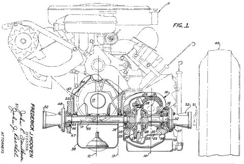
Diagram illustrating the operation of a 2-stroke engine, detailing the positions of the piston and valves relative to the cylinder.
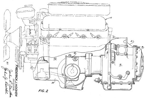
.________.____..________._- 10 15 20 25 30 35 40 50 55 60 988,378 inlet ports 18 opening out of the manifold 17. A piston 20 having piston rings 21 is arranged to reciprocate in the liner 16 and is connected by means of a gudgeon pin 22 and connect~ ing rod 23 to the crank pin 24 of a crank- shaft 25 supported in the crank case 10. A cylinder head 26 is attached by bolts 27 to the block 15 and has in it an ahaust port 28 arranged to be closed by a poppet valve 30 sliding in a valve guide 31 and arranged to be opened by a cam 32 against the action of a valve spring 33. The valve is placed in the centre of the cylinder head with a fuel injection nozzle 34 disposed to one side of It. Integrally arranged in the cylinder head 26 is an exhaust manifold 35 into which the ex- haust port 28 leads and to which is attached an exhaust pipe 36 having located in it a buttery valve 37. The exhaust pipe 36 leads into a combustion chamber 38 contain- ing a socalled ame tube 40 and a fuel in jection device 41 supplied with fuel from a pipe 42. Leading from the combustion chamber 38 is a passage 43 arranged to carry the products of combustion into the plenum chamber 44 of a turbine 45. From the chamber 44 the combustion gases pass through a nozzle ring 46 out on to the blade ring 47 of the rotor 48 attached to an output shaft 50 rotating in bearings 51. The combus- tion gases then pass into a chamber 52 and thence to exhaust. The operating cycle of the 2stroke engine of Figure 1 is shown diagrammatically in Figure 2 where, for convenience, the inlet port is denoted by 18 and the exhaust port by 28, the volume of the combustion chamber when the piston is at top dead centre by v, the volumetric displacement of the piston at the point of opening of the inlet port by Ve, and the volume swept by the piston during the compression period by Vc. The compres- v+Vc sion ratio is determined by the v point at which the exhaust valve closes and is v+Ve related to the expansion ration v in such a way that the pressure of the gases at the end of the expansion stroke is lower than the pressure of the air entering at the inlet 18. The position of the crank pin at top dead centre is represented by A, the position a: the point of opening of the inlet port 18 by B, the position at which the ex haust valve opens by C, the position at which the inlet port closes by D and the position of closing of the exhaust valve by E. For simplicity the operating cycle will be con- sidered as starting at the point when the piston is at top dead centre at the beginning of the working stroke. During the working stroke the piston descends while the crank pin moves from point A to point B at which point the inlet port 18 is uncovered and the gases are at a pressure below atmOSpheric pressure owing to the expansion ratio, and air is sucked in. The inlet port remains open until the crank pin reaches the point D when the inlet port is closed and at this point the cylinder will contain a mixture of residual gases and atmospheric air at approxi mately atmospheric pressure, the quantity of air admitted being much greater than that which will be retained in the cylinder for the combustion of fuel the relative proportions of air and residual gases being dependant upon the pressure at the beginning of the expansion and the expansion ratio. The gases will also be at a relatively low tempera- ture due to the high expansion ratio and the resultant mixture with atmospheric air pro- duces a mean temperature sufciently low to be of value as a cooling agent. The exhaust valve 28 opens slightly before the inlet port closes so that further upward movement of the piston expcls the mixture of gases through the exhaust port. This part of the cycle is devoted to cooling and ejection of the ex haust gases which continues until the crank pin teaches the point E when the exhaust valve is closed, The gases are then com- pressed in the normal manner as the piston returns to the top dead centre position at which the cycle starts again. The expan sion ratio of the engine is sufciently high to ensure that the pressure in the cylinder at the instant of inlet port opening is sufci ently below that of the source of air in the supply to produce a sufcient ow of air into the cylinder to cool the working parts and also to ensure that the temperature of the gases at the end of the expansion period is low enough to have a cooling effect. The expansion ratio may therefore be of the order of 75:1 or higher. Although the compression ratio has a lower value than the expansion ratio it may be greater than the compression ratio normally used, the actual value only being limited by the maximum pressure regarded as permissible in the cylinder during combustion. In a. normal unsupercharged compression ignition engine as hitherto made the compression ratio is of the order of between 14 and 20:1 and the weight of fuel burnt per cycle is about 1/20th of the weight of air trapped in the cylinder (air fuel ratio 20: 1) The resultant pressure rise due to combustion added to the compression pressure, establishes the maxi- mum pressure attainecl in the cylinder, this being an important limitation in the engine design which cannot be exceeded without damage to the engine. If the engine is supercharged some compression takes place outside the cylinder and the compression pressure attained in the cylinder and the weight of air trapped in the cylinder are 65 70 75 80 85 100 105 110 115 120 125
Comments
More from this build


No comments yet.