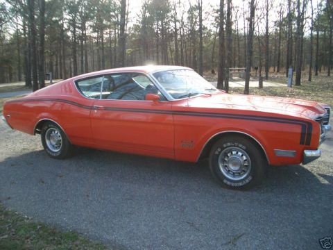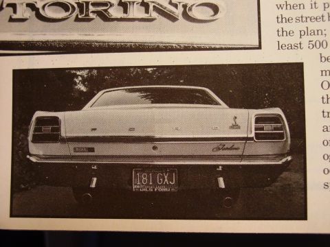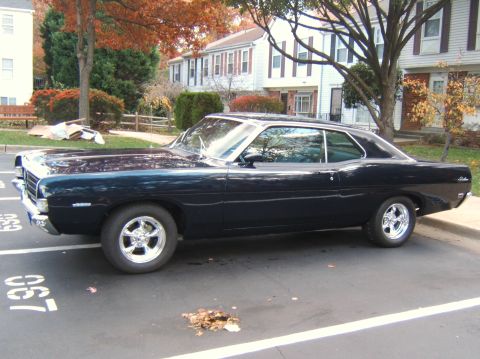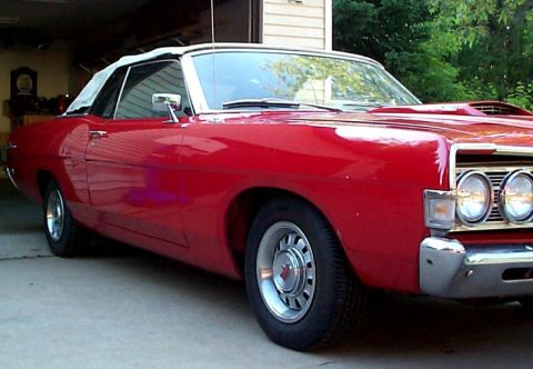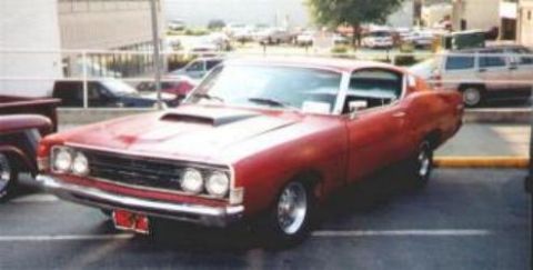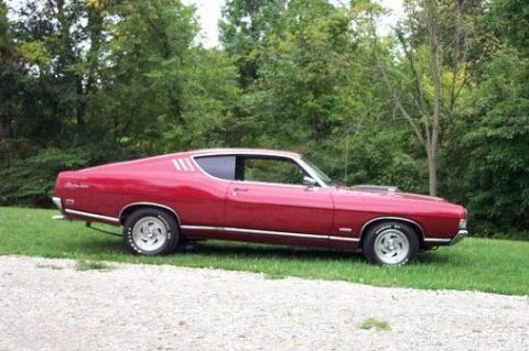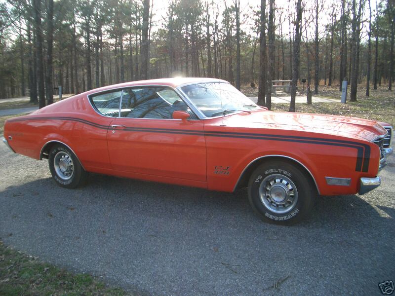
The 1968-1969 Ford Fairlane was the sixth and final full generation of the nameplate, redesigned on Ford's 116 inch wheelbase intermediate platform (113 inches for wagons) and repositioned as the lower series of the new Torino family. Fairlane and Fairlane 500 sat below Torino and Torino GT, sharing the same body shells, engines, and running gear. The base engine was a 200 cubic inch six in 1968 and a new 250 six in 1969, with V8 choices running from the 302 through the 390 and, for 1969, the 351 Windsor. Even the 428 Cobra Jet reached Fairlane-badged cars: it was a rare option on the Fairlane 500 from April 1968, and the 1969 Cobra that carried it as standard equipment was built on Fairlane 500 body codes.
Other Ford Fairlane generations
Platform and Position in the Lineup
Ford redesigned its intermediate line for 1968 and split it into two tiers. Fairlane and Fairlane 500 were the lower series; Torino and Torino GT were the upper. Every one of them rode the same unit-body platform on a 116 inch wheelbase, with station wagons on a 113 inch wheelbase. Suspension was conventional for the class, coil springs and unequal-length control arms up front, a live axle on longitudinal leaf springs in back, drum brakes at all four corners standard with front discs optional. The 1968-1969 Fairlane is the same car underneath as a Torino, so most mechanical parts interchange freely.
Engines
The base engine for 1968 was the 200 cubic inch inline six rated at 115 hp gross. For 1969 a new 250 cubic inch six at 155 hp gross replaced it as standard on everything but the Torino GT and Cobra. The V8 story starts with an oddity: a six-week UAW strike early in the 1968 model year pushed Ford to make the 289 two-barrel, rated 195 hp gross, the base V8 on early cars before the 302 two-barrel took over at 210 hp. A four-barrel 302 rated at 230 hp was offered in 1968 only, and the two-barrel 302 was rerated to 220 hp for 1969. The 390 FE big block came as a 265 hp two-barrel and a 325 hp four-barrel S-code in 1968; for 1969 the two-barrel version was dropped and the four-barrel carried a 320 hp rating. The new 351 Windsor slotted into the middle of the 1969 lineup, 250 hp gross with a two-barrel and 290 hp with a four-barrel, and it quickly became the sensible pick for a driver. Ford's earliest 1968 literature listed a 427, but no Fairlanes or Torinos were actually built with it. From April 1, 1968 the 428 Cobra Jet, rated at a conservative 335 hp gross, went on the option chart for the intermediate line, Fairlane 500 two-doors included; only about 22 Fairlane-badged CJ cars were built that first year. For 1969 the CJ came standard in the new Cobra and remained available elsewhere in the line. All ratings from this era are SAE gross figures, so expect real-world output well below the advertised numbers by modern net measurement.
Drivetrain and Transmissions
Every 1968-1969 Fairlane is front engine, rear wheel drive. A column-shifted 3-speed manual was standard with everything except the 428. A 4-speed manual was available with the stronger V8s, though the 1968 Cobra Jet cars came only with the Cruise-O-Matic automatic; the 4-speed joined the CJ for 1969, when the Cobra made it standard. The Cruise-O-Matic 3-speed automatic was the common choice on cars ordered new, typically a C4 behind the six and small V8s and an FMX or C6 behind the bigger engines depending on application. Ford practice put the 8 inch rear axle behind the six and small V8s and the 9 inch axle behind the big blocks and heavy-duty applications. Limited slip was optional.
Year-by-Year Changes
- 1968: All-new body and the debut of the two-tier Fairlane/Torino structure. Fairlane offered a 2-door hardtop, 4-door sedan, and wagon; Fairlane 500 added a fastback 2-door and convertible. Federally mandated side marker lights appeared this year. Early cars carried the 289 as base V8 during the UAW strike, and the 428 Cobra Jet arrived on April 1.
- 1969: Mild grille and trim revisions. The 250 six replaced the 200 as base engine, the 302 two-barrel picked up 10 hp to 220, the 351 Windsor joined the chart, the four-barrel 302 and two-barrel 390 were dropped, and the Cobra arrived with the 428 CJ and a 4-speed standard. Fairlane-badged cars carried on unchanged in mission, the plain-trim versions of the same body.
Trims and Variants
Fairlane was the base trim, with rubber floor mats and minimal brightwork. Fairlane 500 added upgraded interior trim, more exterior moldings, and the wider body-style selection including the SportsRoof fastback and the convertible. Torino and Torino GT sat above them with nicer trim and, on the GT, standard V8 power. The 1969 Cobra is the interesting footnote for Fairlane people: Ford's literature badged it simply Cobra, but it was built on Fairlane 500 body codes with the 428 CJ, competition suspension, and a 4-speed standard. For a buyer today, a Fairlane 500 fastback with the 390 or the 1969 351 four-barrel gets most of the Torino GT experience at a lower entry price, since the sheet metal and chassis are identical.
End of the Nameplate
The Fairlane name made its true last appearance in 1970, when the Fairlane 500 hung on for one final year as the base series of the restyled Torino line. After 1970 the entire intermediate range was badged Torino, closing out a nameplate Ford had used since 1955.
Asked all the time
What engines came in the 1968-1969 Ford Fairlane?
The 1968 Ford Fairlane started with a 200 cubic inch inline six at 115 hp gross; for 1969 a 250 six at 155 hp became standard. V8 options were the early-1968 289 two-barrel (195 hp, fitted during the UAW strike), the 302 two-barrel (210 hp in 1968, 220 in 1969), a 1968-only 302 four-barrel (230 hp), the 390 FE as a 265 hp two-barrel and 325 hp four-barrel in 1968 (320 hp four-barrel only in 1969), the new-for-1969 351 Windsor at 250 hp (2V) or 290 hp (4V), and from April 1968 the 428 Cobra Jet at 335 hp gross as a rare option.
What is the difference between a 1968-1969 Fairlane and a Torino?
Trim level, not machinery. For 1968-1969 Fairlane and Fairlane 500 were the lower series and Torino and Torino GT the upper series of the same Ford intermediate line. They share the 116 inch wheelbase unit body, engines, transmissions, and axles, so a Fairlane 500 with a 390 is mechanically the same car as a Torino GT with plainer trim.
Which year of the sixth-generation Ford Fairlane should I look for?
For the 1968-1969 Ford Fairlane, 1969 is the better driver's year because the 351 Windsor four-barrel (290 hp gross) became available, a lighter and more parts-friendly engine than the 390 FE. The most collectible Fairlane-badged cars are the roughly 22 1968 Fairlane 500s built with the 428 Cobra Jet, followed by S-code 390 four-barrel cars. Condition matters more than year; the two are nearly identical cars.
Did the 1968-1969 Ford Fairlane come with the 428 Cobra Jet?
Yes, though rarely. The 428 Cobra Jet (335 hp gross) went on the option chart on April 1, 1968, and Fairlane 500 two-doors could be ordered with it; only about 22 Fairlane-badged CJ cars were built for 1968, all with the Cruise-O-Matic automatic. For 1969 the CJ was standard in the Cobra, which was itself built on Fairlane 500 body codes, and it remained optional elsewhere in the line.
What transmissions were available in the 1968-1969 Ford Fairlane?
The 1968-1969 Ford Fairlane came standard with a column-shifted 3-speed manual on everything except the 428. A 4-speed manual was optional with the larger V8s, though 1968 Cobra Jet cars were automatic-only, with the 4-speed added for 1969. The Cruise-O-Matic 3-speed automatic was widely ordered, typically a C4 behind the six and small V8s and heavier FMX or C6 units behind the big engines.
When did Ford stop using the Fairlane name?
After 1970. The 1968-1969 cars were the last full Fairlane generation, and for 1970 only the Fairlane 500 name survived as the base series of the restyled Torino line. From 1971 the entire Ford intermediate range was badged Torino.
Technical Reference
Member-uploaded diagrams & documents for this generation. AI-classified; community-verified where badged.
Data/Spec Plates (2)
- 1969 Ford Torino GT Sportsroof Marti Report - Options, Build Dates & StatisticsThis document is a portion of a Marti Report (Ford production records report signed by Kevin Marti) for a 1969 Ford Torino GT 2-Door Sportsroof. It shows the vehicle was a FLEET order (DSO item # 8607) placed through…
- 1969 Ford Torino GT 428 CJ Marti Report - Door Data Plate Decode & Build DatesThis document is a Marti Auto Works "Deluxe Report" (an Official Licensed Product of Ford Motor Company, copyright Kevin Marti 2003) decoding the factory build data for a 1969 Ford Torino GT with serial number…
Manual Pages (3)
- Chatterton Simplic Two-Stroke Engine - Some Unusual Engines, Page 44 (2 of 3)This is page 44 from a book chapter titled "Some Unusual Engines," describing the operating cycle of the Chatterton "Simplic" two-stroke engine (per the uploader's filename, this is page 2 of 3). The text explains how…
- Chatterton Simplic Hyper-Expansion Engine - Some Unusual Engines p.46 (Setright)This is a scanned page (page 46) from the 1975 book "Some Unusual Engines" by L.J.K. Setright, published by Mechanical Engineering Publications Limited, reproduced with permission from The Institution of Mechanical…
- British Patent 988,378 Page 2 - Chatterton Hyperexpansion 2-Stroke Engine CycleThis is page 2 of British Patent 988,378 (the "Chatterton hyperexpansion" engine patent), describing a 2-stroke compression-ignition engine with an extremely high expansion ratio. The page continues the mechanical…
Schematics (21)
- GB Patent 988378 Fig. 2 - Hyper-Expansion Engine Valve & Port Timing DiagramThis is a scanned sheet from British Complete Specification (patent) No. 988378, labeled as a reproduction of the original drawing on a reduced scale (2 sheets, Sheets 1 & 2). The page shows FIG. 2, a schematic diagram…
- Chatterton Hyperexpansion Engine Patent Drawing Fig. 1 - GB 988378 SchematicThis document is a single-page patent-style line drawing labeled 'Fig. 1.' It is a sectional (cutaway) schematic of an unconventional internal-combustion engine arrangement. On the right side, a cylinder assembly is…
- Engine 3D CAD Cutaway - Crankshaft, Pistons & Cylinder Head Section View (Fig 72e)This document is a color 3D CAD cutaway rendering of an internal combustion engine, apparently one figure ('fig 72e') from a multi-page set of engine illustrations. The section view exposes the interior of the engine…
- 3D CAD Cutaway Render - 4-Cylinder Ported-Liner Engine Crank & Rod AssemblyThis document is not a textual schematic but a full-color 3D CAD rendering (consistent with SolidWorks output) of an internal-combustion engine's rotating and reciprocating assembly, shown in cutaway. It depicts four…
- Engine Cylinder Cross-Section CAD Diagram - Piston, Rod & Liner Cutaway FigureThis image is a computer-generated (CAD) cross-sectional rendering of an internal combustion engine cylinder assembly, shown without any text, labels, or dimensions. The cutaway view uses distinct colors to…
- Single-Cylinder Engine CAD Cutaway Views - IPC Engine 2011 Fig 17a SchematicThis document is not a wiring or fuse diagram but a set of three computer-generated (CAD) cutaway renderings of a single-cylinder internal-combustion engine, shown from a frontal section view and two three-quarter…
- IPC Engine 2011 Fig 21a - 3D Cutaway of Piston, Rod & Cylinder Liner ConceptThis document is a computer-generated 3D cutaway (cross-section) illustration of an internal combustion engine cylinder assembly, apparently from an 'IPC engine 2011' figure series (filename indicates Fig. 21a). The…
- IPC Engine 2011 Fig 20a - Piston & Connecting Rod CAD Cross-Section DiagramThis document is a color CAD-style cross-sectional illustration, apparently a figure (labeled 'fig20a' in the filename) from a series about internal combustion engine design. The image shows a vertical section through…
- IPC Engine 2011 Fig 16a - 3D CAD Cutaway of Piston, Rod & Gear DriveThis document is a computer-generated 3D CAD cutaway illustration of an internal combustion engine, apparently a single-cylinder or one cylinder of a multi-cylinder design shown in section. Visible components include a…
- Inline 4-Cylinder Engine CAD Animation - Crankshaft, Pistons & Linkage SchematicThis image is a computer-generated (CAD) 3D rendering, apparently a frame from an animation, depicting the reciprocating assembly of an inline four-cylinder internal combustion engine. Visible components include four…
- Cutaway 3D CAD Rendering of Unusual Multi-Cylinder Engine: IPC Engine Fig 11aThis file is not a text document but a computer-generated 3D cutaway illustration (an animated GIF frame) of an unconventional multi-cylinder inline engine. The sectioned view exposes the internal architecture: a dark…
- Insulated Pulse Engine Concept CAD Rendering - 3.2L 65 HP 2-Stroke, Rev. 2011This document is a 3D CAD rendering (concept illustration, figure 50a of a multi-figure set) showing two views of an experimental 'Insulated Pulse Engine', a 3.2 litre, 65 horsepower, 2-stroke concept engine, revision…
- Engine Cylinder Cross-Section Schematic - Piston, Injector & Connecting Rod (Fig 20a)This document is a purely graphical, unlabeled color schematic (CAD-style cross-section) of an internal combustion engine cylinder assembly. It appears to be figure 20a from a 2011 engine-related source, based on the…
- IPC Engine 2011 Fig 12a - Cutaway CAD of Pistons, Linkage Rods & CrankshaftThis document is not a text schematic but a 3D CAD rendering of an unconventional internal combustion engine's reciprocating assembly, shown in cutaway. It shows four ported cylinder liners in cross-section, each…
- Engine Cutaway CAD Rendering - Inline Multi-Cylinder Cross-Section DiagramThis image is not a text-bearing schematic but a detailed, full-color 3D CAD cross-section rendering of an inline multi-cylinder reciprocating engine. The cutaway view exposes the internal architecture: a geared…
- IPC Engine Fig 66c - Cross-Section Schematic Drawing (Unusual Engine Design)This document is a black-and-white line drawing (CAD-style cross-sectional schematic) of a complex mechanical assembly. The drawing shows a longitudinal section through what appears to be a cylindrical mechanism with a…
- IPC Engine Fig 65: Cylindrical Rotor/Engine Assembly Line Drawing (Schematic)This document is a text-free line drawing (schematic-style illustration) uploaded to a SuperMotors.net gallery as part of a multi-page set of engine-patent/IPC engine figures. The image depicts a cylindrical mechanical…
- IPC Engine Fig 64c - Piston/Drum Assembly Isometric Schematic DrawingThis document is an untitled, unlabeled line-art engineering illustration, apparently one figure ('Fig 64c') from a multi-page set of engine-concept drawings uploaded alongside other 'IPCengine' figures and pages of a…
- Engine Crankshaft & Gear Train Drive Diagram - CAD Line Drawing (Fig 62c)This document is a text-free technical line drawing, apparently a figure from an engine reference set (filename suggests 'IPC engine Fig 62c'). It depicts, in isometric wireframe style, a complete engine crankshaft…
- Piston & Connecting Rod Assembly Line Drawing - IPC Engine Figure 61cThis document is an untitled, unlabeled line drawing (schematic-style illustration) of an engine piston and connecting rod assembly. The piston is drawn from an angle looking across the crown toward the connecting rod…
- Von Mises Stress FEA Plot - CapSaddle5 Modal Analysis Mode 7 Result WindowThis document is a screenshot of a finite element analysis (FEA) result window, not a traditional automotive schematic. It displays a von Mises stress (Maximum) contour plot with averaged values on a deformed original…
Exploded Parts (1)
- Insulated Pulse Engine 3.2L 2-Stroke Concept Rev. 2011 - Exploded Block DiagramThis document is a black-and-white CAD-style exploded parts drawing of a concept engine block assembly labeled "Insulated Pulse Engine: 3.2 Liter 2-Stroke Concept Rev. 2011." The isometric line drawing shows a…
The wall · registered 1968-1969 Fairlanes
Sorted by depth of documentation. Click any vehicle to open its permanent record.