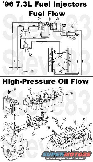
File 442 of 463
Prev | Next

Share This
Url
Tag
Img
Thumb

96f350dieselfuel.jpg Fuel Supply System consists of the following three major subsystems: 

Fuel supply system 
Injection control pressure system 
Fuel injector assembly 

The tandem fuel pump is a camshaft-driven, two-stage diaphragm/piston pump mounted in the engine "V." 

Fuel is drawn from the fuel tank through the primary filter by the diaphragm section of the tandem fuel pump. Pressurized fuel (approximately 28 kPa [4 psi]) is supplied to the secondary filter and returned to the second stage of the tandem fuel pump. The piston-actuated second stage of the tandem fuel pump supplies 276-345 kPa (40-50 psi) of fuel to the rear of each cylinder head where it flows to a fuel rail machined in each cylinder head. 

Drillings in the cylinder head route the fuel to the plunger area of the fuel injector which can pressurize the fuel to 124 MPa (18,000 psi) for delivery to the combustion chamber via a conventional nozzle/valve tip arrangement. 

Return fuel is plumbed from fittings at the front of each cylinder head to a regulator block which contains a piston/spring type regulator valve that maintains pressure to approximately 345 kPa (50 psi). A de-aeration bleed orifice between the fuel filter and the regulator block vents air trapped in the fuel filter. Most of the fuel from the regulator is recirculated to the inlet of the piston (high pressure) stage of the transfer pump. Fuel return to the tank is limited by the fuel filler bleed orifice and a 0.0008mm (.020-inch) fuel return bleed orifice. This prevents the fuel from overheating in the tank.

1  9N184  Fuel Filter  
2  %u2014  Tank Return Orifices (Part of 9155)  
3  %u2014  Strainer Assembly (Part of 9155)  
4  %u2014  Fuel Pressure Regulator (Part of 9155)  
5  9F597  Schrader Valve  
6  1825115C91  Cylinder Heads  
7  9D308  Fuel Return Tube (LH)  
8  9B273  Fuel Return Tube (RH)  
9  %u2014  Piston Stage (Part of 9350)  
10  %u2014  Diaphragm Stage (Part of 9350) 
11  9002  Fuel Tank  

Injection Pressure Control 
The system uses hydraulically actuated injectors to pressurize the fuel inside the injectors. The hydraulic fluid, used to actuate the injectors, is engine oil. 

Oil is drawn from the oil pan through the pickup tube by the engine oil pump. The engine oil pump is a gerotor-type pump driven by the crankshaft. Oil is fed through passages in the front cover to an oil reservoir mounted on top of the front cover. 

The reservoir makes available a constant supply of oil to a high pressure hydraulic pump mounted in the engine "V." The high pressure pump is a gear-driven seven-plunger swash plate pump. High pressure oil is delivered by the high pressure pump to oil rails machined into the cylinder heads. 

When an injector is electrically energized, a poppet valve is opened by an electronic solenoid mounted on the injector. Oil pressure is allowed to flow into the injector and act on the amplifier piston. When injection is ended, the pressure on top of the amplifier piston is vented by the poppet valve through the top portion of the injector and directed by the oil troughs mounted on the injector to a push tube hole for return to the crankcase.

1  1825263C91  Oil Pressure Sensor  
2  1825115C91  Cylinder Head, Right  
3  %u2014  To Crankcase  
4  9J323  High Pressure Oil Pump Supply Hose (RH)  
5  9A332  High Pressure Oil Pump Supply Hose (LH)  
6  %u2014  Cylinder Head High Pressure Rail (Part of 1825115C91)  
7  %u2014  Injector Return  
8  1825115C91  Cylinder Head, Left  
9  9E527  Fuel Injector  
10  9F838  Injection Control Pressure (ICP) Sensor  
11  1825250C91  Injection Pressure Regulator (IPR)  
12  1825259C91  High Pressure Oil Pump  
13  %u2014  From Engine  
14  %u2014  Bleed Hole (Part of 1823534C2)  
15  1823534C2  High Pressure Oil Pump Supply Reservoir 

Injector Driver Module 
The injector driver module (IDM) is used in conjunction with the PCM to sequentially control power to the fuel injectors on the 7.3L DI turbo diesel engine. The PCM processor generates two digital control signals for the IDM: fuel delivery control signal (FDCS) and cylinder identification (CID). The FDCS signal is used by the IDM to control injection timing and injection duration. The CID provides synchronization to the engine's first and fifth injector (firing order). The IDM verifies that FDCS and CID occur at valid timing intervals. The IDM outputs an electronic feedback (EF) signal, to the PCM, which is a delayed mimic of the FDCS for verification. Selected diagnostic information is also passed to the PCM via the EF signal in run mode. 

The IDM is a high-energy power supply which acts as an energy distributor to provide regulated injector energy and control to the unit fuel injectors, based on FDCS and CID commands from the PCM. All IDM components are solid state; there are no user serviceable parts or adjustments. The IDM internal power supply uses a DC-to-DC converter to boost the supply voltage (VBATT) up to 115V DC. This supply is required to overcome the initial impedance of the injectors, ensuring rapid turn on. There are two high side drivers, one for each bank (left and right cylinder bank), and eight low side drivers, one for each injector. One high and one low side must be turned on to energize an injector. Once synchronized with the PCM, the IDM will select the proper low side driver (enable) and control the corresponding high side driver to regulate the current to an injector. 

Continuous and on-demand system diagnostic information is provided between the PCM processor and the IDM via the EF signal. During normal operation, the IDM can indicate to the PCM that an injector low side short to ground has been detected, or that the IDM has lost synchronization. 

The IDM constantly performs self-diagnostics and also monitors the injector circuits for electrical faults. Any fault codes set are transmitted via the EF signal to the PCM during Key On/Engine Off On-Demand Self Test. If the PCM is unable to obtain diagnostic information from the IDM, DTC 1668 is set.

See also:
[url=https://www.supermotors.net/registry/media/1099335][img]https://www.supermotors.net/getfile/1099335/thumbnail/glowplugrelaytime.jpg[/img][/url] . [url=https://www.supermotors.net/registry/media/1124311][img]https://www.supermotors.net/getfile/1124311/thumbnail/96f350dieselgprwts.jpg[/img][/url]
96f350dieselfuel.jpg | Hits: 1729 | Posted on: 11/18/17 | View original size (161.88 KB)

Fuel Supply System consists of the following three major subsystems:

Fuel supply system
Injection control pressure system
Fuel injector assembly

The tandem fuel pump is a camshaft-driven, two-stage diaphragm/piston pump mounted in the engine "V."

Fuel is drawn from the fuel tank through the primary filter by the diaphragm section of the tandem fuel pump. Pressurized fuel (approximately 28 kPa [4 psi]) is supplied to the secondary filter and returned to the second stage of the tandem fuel pump. The piston-actuated second stage of the tandem fuel pump supplies 276-345 kPa (40-50 psi) of fuel to the rear of each cylinder head where it flows to a fuel rail machined in each cylinder head.

Drillings in the cylinder head route the fuel to the plunger area of the fuel injector which can pressurize the fuel to 124 MPa (18,000 psi) for delivery to the combustion chamber via a conventional nozzle/valve tip arrangement.

Return fuel is plumbed from fittings at the front of each cylinder head to a regulator block which contains a piston/spring type regulator valve that maintains pressure to approximately 345 kPa (50 psi). A de-aeration bleed orifice between the fuel filter and the regulator block vents air trapped in the fuel filter. Most of the fuel from the regulator is recirculated to the inlet of the piston (high pressure) stage of the transfer pump. Fuel return to the tank is limited by the fuel filler bleed orifice and a 0.0008mm (.020-inch) fuel return bleed orifice. This prevents the fuel from overheating in the tank.

1 9N184 Fuel Filter
2 %u2014 Tank Return Orifices (Part of 9155)
3 %u2014 Strainer Assembly (Part of 9155)
4 %u2014 Fuel Pressure Regulator (Part of 9155)
5 9F597 Schrader Valve
6 1825115C91 Cylinder Heads
7 9D308 Fuel Return Tube (LH)
8 9B273 Fuel Return Tube (RH)
9 %u2014 Piston Stage (Part of 9350)
10 %u2014 Diaphragm Stage (Part of 9350)
11 9002 Fuel Tank

Injection Pressure Control
The system uses hydraulically actuated injectors to pressurize the fuel inside the injectors. The hydraulic fluid, used to actuate the injectors, is engine oil.

Oil is drawn from the oil pan through the pickup tube by the engine oil pump. The engine oil pump is a gerotor-type pump driven by the crankshaft. Oil is fed through passages in the front cover to an oil reservoir mounted on top of the front cover.

The reservoir makes available a constant supply of oil to a high pressure hydraulic pump mounted in the engine "V." The high pressure pump is a gear-driven seven-plunger swash plate pump. High pressure oil is delivered by the high pressure pump to oil rails machined into the cylinder heads.

When an injector is electrically energized, a poppet valve is opened by an electronic solenoid mounted on the injector. Oil pressure is allowed to flow into the injector and act on the amplifier piston. When injection is ended, the pressure on top of the amplifier piston is vented by the poppet valve through the top portion of the injector and directed by the oil troughs mounted on the injector to a push tube hole for return to the crankcase.

1 1825263C91 Oil Pressure Sensor
2 1825115C91 Cylinder Head, Right
3 %u2014 To Crankcase
4 9J323 High Pressure Oil Pump Supply Hose (RH)
5 9A332 High Pressure Oil Pump Supply Hose (LH)
6 %u2014 Cylinder Head High Pressure Rail (Part of 1825115C91)
7 %u2014 Injector Return
8 1825115C91 Cylinder Head, Left
9 9E527 Fuel Injector
10 9F838 Injection Control Pressure (ICP) Sensor
11 1825250C91 Injection Pressure Regulator (IPR)
12 1825259C91 High Pressure Oil Pump
13 %u2014 From Engine
14 %u2014 Bleed Hole (Part of 1823534C2)
15 1823534C2 High Pressure Oil Pump Supply Reservoir

Injector Driver Module
The injector driver module (IDM) is used in conjunction with the PCM to sequentially control power to the fuel injectors on the 7.3L DI turbo diesel engine. The PCM processor generates two digital control signals for the IDM: fuel delivery control signal (FDCS) and cylinder identification (CID). The FDCS signal is used by the IDM to control injection timing and injection duration. The CID provides synchronization to the engine's first and fifth injector (firing order). The IDM verifies that FDCS and CID occur at valid timing intervals. The IDM outputs an electronic feedback (EF) signal, to the PCM, which is a delayed mimic of the FDCS for verification. Selected diagnostic information is also passed to the PCM via the EF signal in run mode.

The IDM is a high-energy power supply which acts as an energy distributor to provide regulated injector energy and control to the unit fuel injectors, based on FDCS and CID commands from the PCM. All IDM components are solid state; there are no user serviceable parts or adjustments. The IDM internal power supply uses a DC-to-DC converter to boost the supply voltage (VBATT) up to 115V DC. This supply is required to overcome the initial impedance of the injectors, ensuring rapid turn on. There are two high side drivers, one for each bank (left and right cylinder bank), and eight low side drivers, one for each injector. One high and one low side must be turned on to energize an injector. Once synchronized with the PCM, the IDM will select the proper low side driver (enable) and control the corresponding high side driver to regulate the current to an injector.

Continuous and on-demand system diagnostic information is provided between the PCM processor and the IDM via the EF signal. During normal operation, the IDM can indicate to the PCM that an injector low side short to ground has been detected, or that the IDM has lost synchronization.

The IDM constantly performs self-diagnostics and also monitors the injector circuits for electrical faults. Any fault codes set are transmitted via the EF signal to the PCM during Key On/Engine Off On-Demand Self Test. If the PCM is unable to obtain diagnostic information from the IDM, DTC 1668 is set.

See also:
.
About SuperMotors | Contact Us | FAQ/Help | Legal
Copyright © 1998-2024 Web Design Solutions, Inc.
All rights reserved. Duplication & reproduction is strictly prohibited.
SuperMotors.net v5.0.2 ChangeLog