Home/
Registry/
Ford/
Bronco/
1980-1986/
“That dirty old truck”/
Photo
supermotors.net/registry/media/1126307
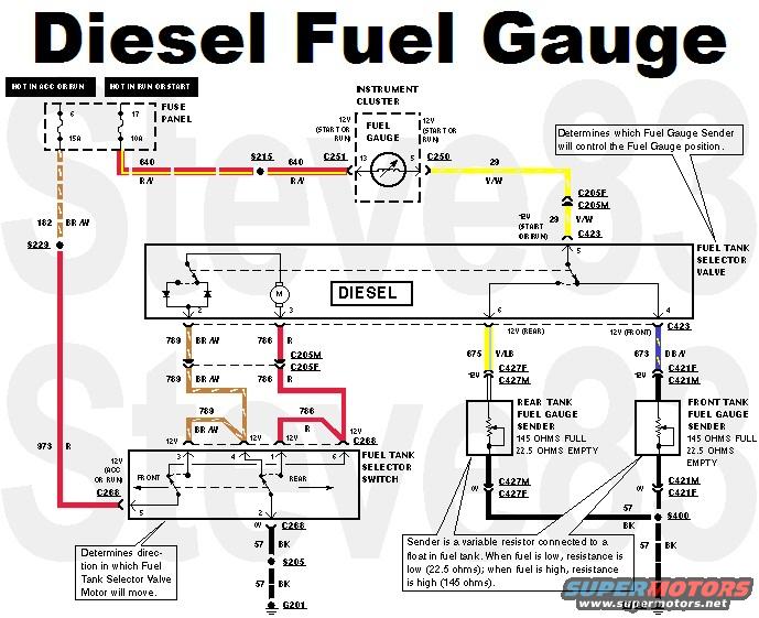
Ford Diesel Dual Fuel Tank Gauge & Selector Valve Wiring Diagram
Reference · 1980-1986 BroncoAll 92 wiring diagrams
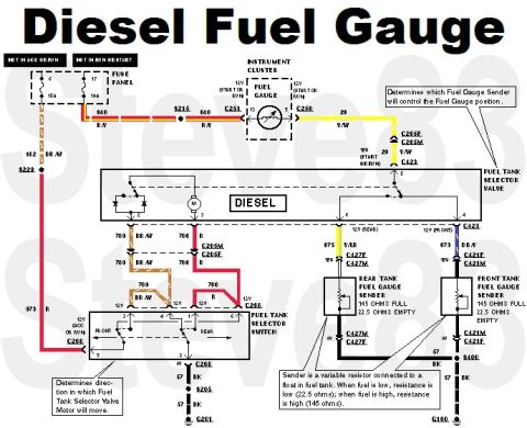






Diesel fuel gauge wiring diagram showing color-coded circuits between fuse panel, instrument cluster, selector valve and tank senders.
Part of 1980-1986 Ford Bronco Wiring Diagrams
This document is a wiring diagram titled 'Diesel Fuel Gauge' showing the dual fuel tank gauge and tank-selection circuit for a Ford diesel truck. Power comes from two fuse panel circuits, a 15A fuse (hot in ACC or RUN) and a 10A fuse (hot in RUN or START), feeding circuit 640 (R/Y) through splice S215 and connector C251 to the instrument cluster fuel gauge. The gauge output leaves on circuit 29 (Y/W) through connectors C205 and C423 to the fuel tank selector valve (marked DIESEL), which determines which fuel gauge sender controls the gauge. The fuel tank selector switch (FRONT/REAR positions, fed by circuit 973 R, 12V in ACC or RUN via C268) controls direction of the selector valve motor via circuits 789 (BR/W) and 786 (R). Sender feeds are circuit 675 (Y/LB) via C427 to the rear tank sender and 673 (DB/Y) via C421 to the front tank sender. Both senders read 145 ohms full and 22.5 ohms empty; a note explains the sender is a variable float resistor. Grounds run on circuit 57 (BK) through splices S205 and S400 to grounds G201 and G100. Connector, splice, and wire color codes are labeled throughout.
Is this accurate? Sign in to help verify it.
Frequently asked questions
- What are the resistance values of the Ford diesel fuel tank senders?
- Both the front and rear tank fuel gauge senders read 145 ohms when full and 22.5 ohms when empty. Resistance is low (22.5 ohms) when fuel is low and high (145 ohms) when fuel is high.
- What fuses power the diesel fuel gauge circuit?
- A 15A fuse (hot in ACC or RUN) and a 10A fuse (hot in RUN or START) in the fuse panel feed circuit 640 (R/Y) to the instrument cluster fuel gauge.
- What does the fuel tank selector valve do?
- The fuel tank selector valve (labeled DIESEL) determines which fuel gauge sender, front or rear tank, will control the fuel gauge position.
- What wire colors go to the front and rear tank senders?
- The rear tank sender is fed by circuit 675 Y/LB through connectors C427F/C427M; the front tank sender is fed by circuit 673 DB/Y through connectors C421F/C421M. Both grounds are circuit 57 BK.
- How does the fuel tank selector switch work?
- The FRONT/REAR selector switch, powered by circuit 973 R (12V in ACC or RUN through C268), determines the direction in which the fuel tank selector valve motor will move via circuits 789 BR/W and 786 R.






No comments yet.