
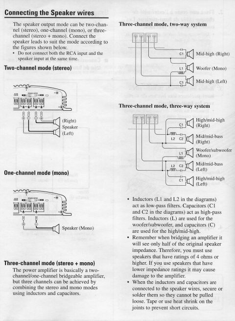
This document details audio filter constants and provides a component selection chart for speaker impedance.
issuing the Filter Constant low-pass filter (for snbwoofer/woofer): Ella/octave High-pass lter (for mid/mid-high): BdB/octave Ci OdB C+>1 7608 93 (l i -. -1 .. Component Guide Band-pass lter (combination of low-pass iilter and high-pass filter for mid- bass/midl: 6 dB/octave (9311151113 i 0:: :1 6 in in lm me 2 - A multi-clmnnel system can he sci up uqing u combination of lters. The inductance (L) and cupuuituncu (C) will determine llic frequency (It) ihnl the Speaker will reproduce. Refer to the chart below to determine the components required, - Use the capacitors specied. Nonepoluri7ed capacitors rated at over :25 V Should be used for C1 and C2 in the d gram. Because of the voltage oulpul of lhc umpliilu, il in very important to use non-polarized capacitors rated at or over 35 V. This will prevent a safely hgimrtl. Speaker load Impedance 2 Q 4 Q 8 52 01112) LimH) C(uF) L(mH) c1010 L(mH) C(uF) 50 6.4 1.600 12.7 800 80 V 4.0 1.000 8.07 E 125 27.5 640 5.1 300 200 1 .6 400 3.2 200 i320 1.0 250 2.0 125 7 Q7 7 V 7 7 770.0477 if 1.3 '80 2.6 40 7 i 800 0,4 100 0,8 50 1.0 25 1,250 0.25 64 0.5 30 1.0 16 72.000 0.16 40 0.3 20 0.64 10 7 7,200 7 7' 0.1 is 0.2 12.5 0.4 6.2 5,000 0.06 16 0.13 s 0.26 8.000 70.04 10 0.08 5 0.167 72.57 76110? 7' 77777 770.703 x 0.00 4 ' 0.13 2
Comments
More from this build
No comments yet.