Homemade All-Thread Rod Tool Diagram - Nuts & Thick Washer Assembly Sketch

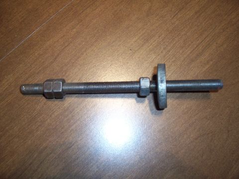
Basic assembly diagram of a threaded all-thread rod showing placement of two nuts, a single nut, and a thick washer.
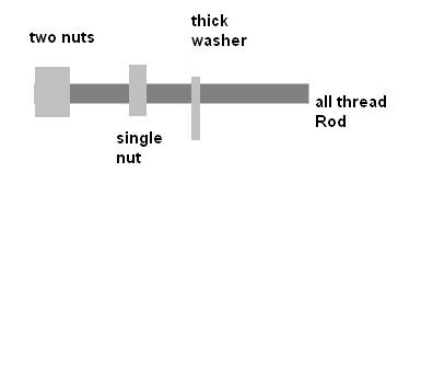
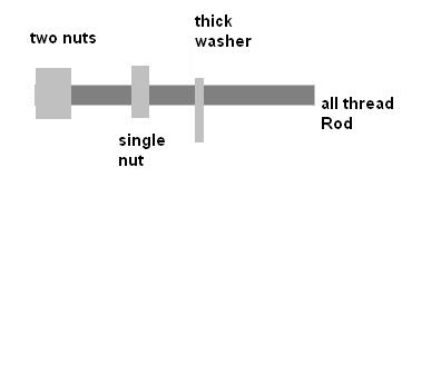
This document is a simple hand-drawn (computer-sketched) diagram of a homemade tool built from an all-thread (threaded) rod. The drawing shows a horizontal threaded rod labeled 'all thread Rod' with hardware positioned along its length: at the left end, 'two nuts' are stacked together (shown as a larger light-gray block), followed by a 'single nut' further along the rod, and then a 'thick washer' shown as a thin vertical plate near the middle of the rod. No dimensions, thread sizes, torque values, part numbers, or vehicle-specific information are provided. The diagram appears intended to illustrate the assembly order of components on a threaded rod, likely for use as a puller, press, or spacer/installation tool in an automotive repair context. A reader can learn the relative arrangement of the nuts and washer on the rod, but must infer sizes and usage from the accompanying repair procedure (not included in this image). The image is a low-resolution JPEG sketch with four text labels, all fully legible.
Is this accurate? Sign in to help verify it.
Frequently asked questions
- What components are shown in this tool diagram?
- An all-thread rod, two nuts stacked at one end, a single nut further along the rod, and a thick washer.
- In what order are the parts arranged on the rod?
- From the left end: two nuts together, then a single nut, then a thick washer, with the remainder of the all-thread rod extending to the right.
- Does the diagram give thread size, rod length, or part numbers?
- No. The diagram only labels the parts (two nuts, single nut, thick washer, all thread rod) with no dimensions or part numbers.
No comments yet.