TSB 92-01-08 (Excerpt) Touch-Drive ESOF Operation
IF THE IMAGE IS TOO SMALL, click it.
Publication Date: JANUARY 6, 1992
LIGHT TRUCK: 1990 and prior BRONCO II
1992 and prior AEROSTAR, BRONCO, F-150, F-250, F-350, RANGER
1991-92 EXPLORER
ISSUE: Ford 4-wheel drive vehicles were discussed at length in the 1991 April, May and June issues of Shop Tips. Topics included locking hubs, transfer cases, vehicle operating characteristics, driveline windup and service tips. This information is being reprinted here to better assist the technician with questions concerning 4WD operation and service.
ACTION: Refer to the following for Ford 4WD information.
"TOUCH DRIVE" - NEW ELECTRONIC CONTROL MODULE FOR 1991
A new electronic control module has been installed on the 1991 model Ford trucks with "Touch Drive," built after 8/6/90. The new module features a different computer logic to control shifting.
With the previous module, it was possible for the driver to select 4L directly from 2WD. However, the control module actually shifted the vehicle into 4H first, then checked to see if the vehicle was stopped and that the automatic transmission was in neutral (or the manual transmission clutch was disengaged). If these conditions were not met, the actual shift wouldn't take place. Instead, everything would be made ready for the moment when the shift could be completed. This was called pre-staging.
During pre-staging, the Low Range light flashed. This confused some customers. In addition, pre-staging and the flashing light sent confusing signals to the new E4OD transmission's electronic controller.
The new module solves both these problems. With the new logic, if the driver selects 4L when in 2WD, nothing will happen, because the transfer case controller ignores the 4L signal. The driver must make the shift to 4H first, then (while stopped) shift to 4L.
These are the six common concerns most often expressed by customers:
1. Nothing happens (dead system).
2. No range shift.
3. Attempt to shift into 4H from 2H or 4L results in the module clicking and chattering and the system stops in 2H.
4. At start up, the vehicle shifts on its own.
5. Indicator lights don't register the correct information.
6. Shifting on the fly isn't smooth and may require stopping in order to complete the shift.
All these conditions can be best understood by taking a close look at a schematic of the electrical system linked below.
******* USE THIS DIAGRAM *******
P1 = ESOF Module Pin A8
P2 = ESOF Module Pin A7
P3 = Electronic Shift Control Switch Pin 8 .
. 
*****************************
Power In
Power is supplied to the system at 3 points: instrument panel fuses 12 (B ), 17 (ig.sw. in Start/Run), & 18 (ig.sw. in Run).
P1. This is a direct connection to the battery. This power drives the electric shift control motor and provides current to the instrument cluster lamps. This circuit goes to ground at G201.
P2. The electronic shift control module is tied into the ignition circuit. This circuit provides power to the computer and goes to ground at G200.
P3. Nighttime illumination is provided by a connection to the vehicle's nighttime illumination circuit, which goes to ground at G201.
The electronic shift control module directs power depending on the position of the control switches. Inputs to and outputs from the shift module are labeled "A", "B" or "C." "A" circuits are power circuits, "B" circuits are data circuits from sensors and "C" circuits are activating switch and related lamp circuits.
The "B" circuits supply data from three sources: The speed sensor, the motor position sensor and either a neutral switch (for automatic transmissions) or a clutch switch (for manual transmissions).
The speed sensor is important because the vehicle must be stopped for a shift into or out of 4L. The shift module won't make the shift if the vehicle is moving. The shift module also won't make a shift to 4L or back unless an automatic transmission is in neutral or the clutch is depressed on a manual transmission.
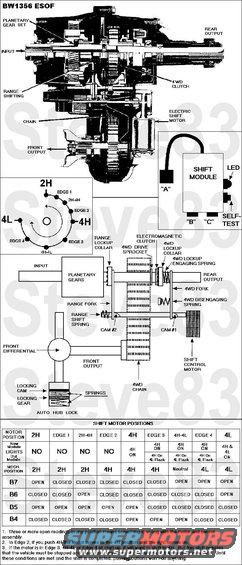
The motor position sensor indicates the position of the shift motor shaft. This shaft turns through approximately 270 degrees and should stop at three indexed points, 2H, 4H and 4L (Figure 20). The shift control module needs to know where the shaft is before making a new shift. When this sensor isn't functioning properly or the motor stops slightly off location, the shift control module may become "confused."
The "C" circuits involve the switches on the vehicle's control panel. When everything is working properly, activating a switch will result in either a shift from 2H to 4H or back, or a shift from 4H to 4L or back. The default operating mode is 2H. This means that in the absence of other instructions, the shift control module will assume that the vehicle should be in 2H. If there is a failure in the system during shifts or engine start up, it will default the vehicle to 2H and permit continued operation.
DIAGNOSIS
With this background, let's diagnose our six problem areas.
1. Nothing Happens (Dead System)
The obvious first step in diagnosing a dead system is to check the power sources, fuses and grounds. If these check out, you should run the shift control module self-test. Figure 22 shows the module with pigtail "A," "B" and "C" attachments. The self-test button and self-test LED are located on the side of the shift control module.
Disconnect the "B" and "C" connectors, turn on the ignition and allow 4 seconds for the module to power up. Then push the self-test button. If the LED doesn't illuminate, the module is dead and must be replaced. If the LED comes on and stays on for 30 seconds, there is an error condition and the module will have to be replaced. If the module is OK the LED will flash 4 times. This test, however, is not 100 percent accurate. During the test, the vehicle isn't operating, so the shift control module isn't receiving data and initiating shifts. If the unit passes the self-test, it's probably a good module. Go on to check for other probable causes, but don't rule out the module entirely. If your search doesn't turn up any other cause, it may be the module after all. You may have to try replacing the module even though it passed the self-test.
Check Sensors
A logical next step is to check the three sensors with the ignition on. The transmission sensors (manual or automatic) should be closed with the clutch in, or the automatic shift in neutral. The speed sensor should show 225-275 ohms with the vehicle stopped. Check at the module connection.
Check both the motor position sensors and the wiring harness at B4, B5, B6 and B7 and the input from B8 (see Figure 21). Make sure the harness is OK first, then check the contacts against the chart in Figure 23. Each valid combination of open and closed switches indicates a different position of the motor. For example, at the 4H position, B7 is closed, B6 is closed, B5 is open and B4 is open. Besides the three main positions (2H, 4H and 4L), intermediate positions are also shown - three between 2H and 4H and three between 4H and 4L (see Figure 20 and the chart in Figure 23). Combinations other than those shown in Figure 23 indicate a defective motor sensor assembly.
Check Transfer Case Motor
To check if the transfer case motor is actually functioning (because it may be hard to hear it in a noisy shop) attach a voltmeter to A4 and A5. Have someone activate a shift and look for a brief (one second) increase in voltage and listen for the relay to click on, then off. If there is power present, then the control module is trying to run the motor. At this point, unbolt the motor and have someone activate a shift again. If the motor doesn't actually turn, it is malfunctioning and must be replaced. If there is no power to the motor, check both the power circuits again and the sensors. If there is incorrect sensor data, the module won't power the motor.
Check Shift Switches
If the problem isn't in the sensors or the motor, you should next check the control panel switches. Make this check with the ignition on. Disconnect the "B" and "C" connections to the sensors, so that their data won't confuse the diagnosis. Now check power at the C1 connection at the module. There should be 5 volts coming from the shift control module to the 4H and 4L switches. Check C1, C2, and C3 for short to ground. You can check the switches themselves by disconnecting C1 and checking continuity across C1 to C2 and C1 to C3. If current passes when the switch buttons are pushed, the switches are OK. Finally, check for a short between C2 and C3 by bridging between them and activating the 4H and 4L buttons. There are situations where wiring harnesses get crushed in such a way that two wires are crushed together and short, even though there is no short to ground.
Check Lamps
To check the lamps, turn the ignition on and ground C4 and C5. The lamps should light.
2. No Range Shift
If the vehicle won't shift into 4L, check the speed sensor and the transmission interlocks (neutral or clutch in). Also check the 4L switch (C3) to see if the module is getting a signal. Be sure to check for corroded connections. If this was the first time the vehicle was ever shifted into 4L, the problem may be a defective part that was there from the beginning, or a component that has frozen due to disuse. Many vehicles are purchased and operated for considerable periods of time before a shift to 4L is made. If the vehicle is brought to the shop in 4L with the report that it won't shift back to 4H, your first check is to follow the proper sequence of being stopped and having the vehicle in neutral (or clutch in) when pushing the switch. If this doesn't do the trick, check the 4L switch and the motor position sensor.
3. Shift From 2H to 4H Results In Chatter and Clicking Noises From The Module, But No Shift
Typically, in this situation the motor hunts for 4H, but overshoots, then hunts back and overshoots the other way. After 7-10 seconds, with lots of clicks and chatter, the module gives up and returns to the default, which is 2H. This problem is normally not the sensor input. It is usually the result of the motor running too fast or braking too slowly to allow the module to position it accurately. The motor must be replaced.
4. At Start Up, the Vehicle Shifts On Its Own
This can occur when the motor position sensor indicates an intermediate position between 4H and 4L. If the vehicle is started in PARK instead of NEUTRAL, when the driver first moves the transmission shift lever to DRIVE, the transmission passes through NEUTRAL. As it passes through NEUTRAL, the shift module activates the shift called for by the misinformation from the motor position sensor. On manual transmissions or automatic transmissions started in NEUTRAL, the shift occurs immediately. This may be a one-time-only event. However, the motor position sensor should be checked if it happens frequently.
5. Indicator Lights Don't Register the Correct Information
There are lights on the dash and LED indicator lights in the switches. If the lights are on all the time, look for a short to ground. Also check to see if the shift control module is activating them all; this is an internal malfunction. If the LED lights, in the buttons, remain on all the time, first check to see if the dash lights are also on. If the dash lights are not on, this means that the dash lights have burned out. The LED lights are on because a low current is still passing across, enough to light the LED. If no lights illuminate as you go through the shifts and ground power and bulbs are good, then the module is at fault or the motor has stopped at an intermediate point.
6. Shifting on the Fly Isn't Smooth and May Require Stopping In Order to Complete the Shift
Look for problems with the electric magnetic clutch. If the ratcheting or grinding goes on for more than four seconds, there may be a problem with power to the clutch from the shift control module, the clutch ground or the clutch itself. Check the wiring harness as well. .
. 
----------------------------------------------------------------------------------
TSB 90-18-10 ELECTRONIC SHIFT MODULE (4X4) - MODIFIED OPERATION
LIGHT TRUCK: 1986-90 BRONCO II
1986-91 BRONCO, RANGER 1991 EXPLORER
ISSUE: The shift procedures into and out of LOW RANGE are revised for Ranger, Bronco and Explorer trucks built after 8/1/90 due to module changes. The new module will also be used to service prior model year trucks.
ACTION: If service is required on models built prior to 8/1/90, advise the customers of the following changes made to their vehicles.
Operation of the 1991 modules have been changed as follows:
To shift into 4 LOW:
^ Truck must be in 4x4 HIGH by previously pressing the 4x4 switch
^ Truck must be stopped (condition A)
^ The clutch must be depressed or the automatic transmission must be in neutral (condition B)
^ Then press LOW RANGE switch
To shift out of 4 LOW:
^ Truck must be stopped (condition A)
^ The clutch must be depressed or the automatic transmission must be in neutral (condition B)
^ Then press the LOW RANGE switch to shift back into 4x4 HIGH
^ Press the 4x4 HIGH switch to shift into 2 HIGH if desired
Previously, the module would respond to the LOW RANGE input from any mode (2H, 4H, 4L). If conditions A and B above are not met, the module would respond by flashing the 4 LOW indicator and wait until conditions A and B are met before completing the shift into or out of LOW RANGE. If LOW RANGE was selected while in 2 HIGH mode, the module would shift to 4 HIGH before flashing the indicator.
PART NUMBER . . PART NAME . . . . . . . . . . . . . CLASS
F1TZ-7E453-A . . . 4X4 Electronic Shift Module . . B
OTHER APPLICABLE ARTICLES: None
WARRANTY STATUS: INFORMATION ONLY
OASIS CODES: 508000
----------------------------------------------------------------------------------
FSA 93S65 1993 F-Series and Bronco 4x4 Vehicles with the Touch-Drive Electric Shift-on-the-Fly Transfer Case (ESOF) (F1TA-7A195-DA)
Check the Ford website &/or the NHTSA to see if your VIN is affected.
Note that this is a safety recall, and any included vehicle will be repaired free, no matter how old it is, how long the owner waits to present it for repair, or how many times it has been sold.
Ford Motor Company has determined that a defect which relates to motor vehicle safety exists in certain 1993 Model Year F-Series and Bronco 4x4 vehicles equipped with the Touch-Drive electric shift transfer cases.
Safety Defect
Some of the affected vehicles may have an electronic transfer case that contains a prior level electric shift motor. In the four-wheel drive "high" mode of operation, the transfer case may shift to "neutral" without input from the driver. This condition may occur while the vehicle is coasting in a forward direction or while engine power is being applied in reverse. The vehicle can be operated normally in the two-wheel drive modes and in the four-wheel drive "low" mode.
WARNING: IF A DRIVER PARKS THE VEHICLE IN THE FOUR-WHEEL DRIVE "HIGH" MODE WITHOUT FULLY SETTING THE PARKING BRAKE, IT COULD ROLL FREELY AS IF IN NEUTRAL CREATING THE POSSIBILITY OF A CRASH OR PERSONAL INJURY.
As stated in the Owner's Guide for your vehicle, Ford recommends that a vehicle operator always set the parking brake when leaving the vehicle unattended.
Repairs
At no charge to you, your dealer will inspect the transfer case and, if necessary, replace it. Dealers currently have instructions and parts ordering information. When you bring your truck in, show the dealer this letter. If you misplace this letter, your dealer will still do the work, free of charge. If the dealer doesn't make the repair promptly and without charge, you may contact the Ford Customer Assistance Center, 300 Renaissance Center, P.O. Box 43360, Detroit, Michigan 48243. You also may send a complaint to the Administrator, National Highway Traffic Safety Administration, 400 Seventh Street, S.W., Washington, D.C. 20590 or call the toll free Auto Safety Hotline 1-800-424-9393 (Washington, D.C. area residents may call 366-0123).
How Long Will It Take?
The time needed for the inspection is approximately one half (1/2) hour. However, due to service scheduling times, your dealer may need your vehicle for one full working day. If the inspection reveals that a new transfer case is needed, it may be necessary for your dealer to order it. Call your dealer without delay.
Courtesy Cars
Should the transfer case of your vehicle require replacement, your dealer will provide you with a free (except for fuel) courtesy car until parts arrive and repairs are completed.
Affected Vehicles: 1993 Model F- Series and Bronco 4x4 Vehicles
Technical Instructions
1. Inspect the electronic transfer case wiring harness (the wiring harness may need to be cleaned for inspection). If the harness is GRAY, DO NOT REPLACE THE TRANSFER CASE. Claim inspect time only.
2. If the harness is BLACK, replace the transfer case as outlined in the appropriate shop manual.
3. Return the removed transfer case, freight prepaid, to:
Warranty Parts Return Center
1285 South Mill Street
Plymouth, MI 48170
c/o Safety Recall 93S65
Labor Allowances
Inspect transfer case wiring harness 0.3 Hrs.
Remove/Install transfer case (includes inspection) 1.5 Hrs.
Order your parts requirements by calling 1-800-325-5621 (Renkim Corporation). When confirmed that a transfer case replacement is required, Renkim will submit the order to have one direct shipped to you.
When calling this number, be prepared to give the following information:
VIN Number
P & A Code
Program Number 93S65
Warranty Repair Order Number
Dealer Name, Address, and Zip Code
Name of contact at dealership
Telephone Number
Color of the wiring harness
Is this accurate? Sign in to help verify it.
Comments
More from this build


No comments yet.