Home/
Registry/
Ford/
Bronco/
1992-1996/
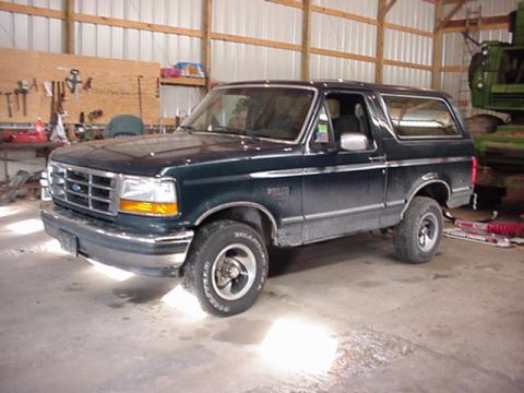
1994 Ford Bronco/
Photo
supermotors.net/registry/media/811529
This document provides detailed instructions for the removal and installation of a steering column, likely for a Ford F-Series truck or Bronco.
I . B-6 Steering Column, F-Super Duty Commercial Chassis = OVAL AND INSTALLATION (Continued) 4. Turn the ignition switch lock cylinder with the ignition switch to ON position. 5. Place 3. 18mm (1 / 8-inch) diameter wire pin or small drift punch in the hole located inside the steering column tube near the base of the housing of the ignition switch lock cylinder. 6. Depress the retaining pin while pulling out on the ignition switch lock cylinder to remove it from the housing of the steering column tube. installation 1. To install the ignition switch lock cylinder, turn the ignition switch lock cylinder to the ON position. 2. Depress the retaining pin. insert the ignition switch lock cylinder into steering actuator housing in the steering column tube flange casting. Ignition switch lock cylinder should be fully sealed and aligned into the interlocking washer before turning the ignition switch to the OFF position allowing retaining pin of ignition switch lock cylinder to extend into the cast housing hole of ignition switch lock cylinder. 3. Using the ignition key, rotate the ignition switch lock cylinder to obtain correct mechanical operation in all positions. 4. Install the steering wheel and trim pads as described in this section. NOTE: When the battery has been disconnected and reconnected, some abnormal drive symptoms may occur while the powertrain control module relearns its adaptive strategy. The vehicle may need to be driven 10 miles or more for powertrain control module to relearn the strategy. 5. Connect the battery ground cable. 6. On vehicles equipped with automatic transmission, check for proper start in neutral. Check that the start circuit cannot be actuated in the drive and reverse positions and the engine (6007) will shutoff in either drive, reverse or neutral. If the engine will not shut off the switch is not adjusted properly. Switch as described in Section 11-05. Removal NOTE: The following procedure applies to vehicles with inoperative steering column tube flange and on which ignition switch lock cylinder cannot be rotated due to lost or broken ignition key, key number not known or cap of ignition switch lock cylinder damaged or broken. 1. Disconnect the battery ground cable. 2. Remove the horn button and steering wheel as described in this section. 3. Remove the turn indicator lever from the steering column tube. 4. Remove the steering column shrouds from the steering column tube. 5. Detach and lower the steering column tube from the brake pedal support bracket as described in this section. 6. Remove the ignition switch and pin it in the LOCK position. 7. Remove the turn indicator switch and mounting plate from the steering column tube as described in the Steering Column Tube Bearing, Upper Flange and Shift Socket / Flange Extension removal and installation procedure in this section. 8. Remove the upper steering column tube bearing snap ring. 9. Remove two T-bolt retaining nuts that secure the steering column tube flange casting to the outer steering column tube. 10. Remove the entire steering column tube flange casting, upper steering column tube bearing, ignition switch lock cylinder, steering column lock lever actuator and ignition switch actuating rod by pulling the assembly over the end of the steering column shaft. Installation NOTE: Retain the ignition switch actuating rod from the removed casting and use it with the new steering column tube flange casting assembly. 1. Replace the ignition switch lock cylinder with a new assembly consisting of: (1) steering column tube flange (1) ignition switch lock cylinder (1) steering column lock gear (1) steering column lock housing bearing (1) steering column upper bearing retainer (3C610) (1) steering column lock lever actuator 2. Reassemble the above parts, installing a new upper steering column tube bearing. 3. Set the steering column lock lever actuator to steering column lock gear as described in this section. 4. Install the turn indicator switch and mounting plate as described in this section. 5. Install the ignition switch and check or adjust for proper function as described in this section. 6. Install the steering column shrouds, steering wheel and steering wheel pad horn switch as described in this section. 7. Install the turn indicator lever. 8. Using the ignition key, rotate the ignition switch lock cylinder to obtain correct mechanical operation in all positions. 9. Install the horn button and steering wheel as described in this section. NOTE: When the battery has been disconnected and reconnected, some abnormal drive symptoms may occur while the powertrain control module relearns its adaptive strategy. The vehicle may need to be driven 10 miles or more for powertrain control module to relearn the strategy. 10. Connect the battery ground cable. 1994 Econoline/F~150, F250, F-asO/Bronco/F-Super Duty Body/Chassis Aug 1993 1 1 -04B-6
Comments
More from this build


No comments yet.