Exploded parts diagram of a Mazda M5OD-R2 manual transmission
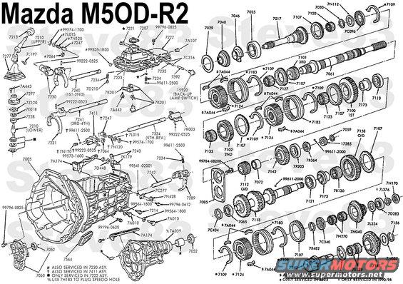
Mazda M5OD-R2 Disassembly
IF THE IMAGE IS TOO SMALL, click it.
M5OD-R2 TRANSMISSION GEAR RATIOS:
1 - 3.90 : 1
2 - 2.25 : 1
3 - 1.50 : 1
4 - 1.00 : 1
5 - 0.80 : 1
R - 3.39 : 1
First Gear
The first/second synchronizer is splined to the output shaft. The first/second synchronizer sleeve locks the first gear (1GR) (7100) to the output shaft through the synchronizer. The input gear drives the countershaft. First gear on the countershaft drives the first gear on the output shaft, which is driven in reduction at 3.90:1.
Second Gear
The synchronizer is splined to the output shaft. The synchronizer sleeve locks second gear to the output shaft through the synchronizer. The input gear drives the countershaft. Second gear on the countershaft drives second gear on the output shaft. The output shaft is driven in reduction at 2.25:1.
Third Gear
The third/fourth synchronizer is splined to the output shaft. The synchronizer sleeve locks third gear to the output shaft through the synchronizer. The input gear drives the countershaft. Third gear on the countershaft drives third gear on the output shaft. The output shaft is driven in reduction at 1.50:1.
Fourth Gear
The third/fourth synchronizer is splined to the output shaft. The synchronizer locks the input shaft (7017) to the output shaft. The input shaft and output shaft turn at the same speed (1:1 ratio).
Fifth Gear (Overdrive)
The fifth gear synchronizer is splined to the countershaft. The synchronizer sleeve locks fifth gear to the countershaft. The input gear drives the countershaft. Fifth gear on the countershaft drives fifth gear which is splined to the output shaft. The output shaft is overdriven at a ratio of 0.80:1.
Reverse Gear
A reverse idler gear produces rotation in the opposite direction of output shaft rotation. The fifth/reverse synchronizer is splined to the countershaft. The synchronizer sleeve locks reverse gear to the countershaft. The input gear drives the countershaft. The countershaft reverse gear drives the reverse idler gear. The reverse idler gear drives reverse gear (which is splined to the output shaft) at a reduction ratio of 3.39:1.
SPECIAL SERVICE TOOL(S) REQUIRED
Description Tool Number
Mainshaft Locknut (7B364) Wrench T88T-7025-AR (55mm hex, sides are 1.20")
Remover/Replacer Tube T75L-7025-B
TOD Forcing Screw T84T-7025-B
Bearing Puller T77J-7025-H
Bearing Collet Sleeve T75L-7025-G
Collet Half T88T-7061-A
Nut 7N170 is 32mm hex
Known problems include:
leaks from shift rail plugs #60 & 61
sensitivity to fluid level & quality
weak shifter susceptible to wear
To remove the upper shifter (7210), remove the 17mm nut from the passenger side of the stud (7L197), and install it on the driver's side. Tighten it until it loosens, then push the stud out to the driver's side. Remove the upper shifter.
http://bbscomp.com/george/manual.pdf
1 ) Remove transmission (7003) from vehicle as outlined in this section. Secure to an appropriate holding fixture.
2 ) Using a 12mm wrench, remove ten retaining bolts. Remove case cover.
3 ) Remove shift control selector lever and housing and gearshift lever boot if necessary.
4 ) Using a 12mm wrench, remove 10 retaining bolts. Remove case cover.
5 ) Remove and discard extension housing seal (4x2 vehicles only).
6 ) Remove extension housing (7A039) from case.
7 ) Remove countershaft rear bearing and thrust washer.
8 ) Using Mainshaft Locknut Wrench T88T-7025-AR and Remover/Replacer Tube T75L-7025-B, remove and discard lock nut from output and fifth gear driveshaft.
9 ) Using a 17mm wrench, remove holding bolt from reverse idler gear shaft (7140). Remove reverse idler gear assembly by grasping and pulling rearward.
10 ) CAUTION: Make sure tools are properly positioned so as not to damage parts being removed.
Remove output shaft bearing (7065) from output shaft using Remover/Replacer Tube T75L-7025-B, TOD Forcing Screw T84T-7025-B and Bearing Puller T77J-7025-H.
11 ) Using a brass drift and hammer, drive reverse gear from output shaft.
12 ) Remove sleeve from output shaft.
13 ) Remove countershaft reverse gear with two reverse idler gear bearings and reverse synchronizer blocking ring (7107).
14 ) Remove thrust washer and split washer from countershaft.
15 ) Using a 12mm wrench, remove holding bolt from reverse gear shift rail (7240).
16 ) Remove the fifth/reverse synchronizer and fifth/reverse gear shifter fork (7230) as an assembly without separating the steel ball and shifter interlock spring (7234) (removed from shift fork groove) unless necessary.
17 ) Remove fifth gear synchronizer blocking ring.
18 ) NOTE: Do not remove the Torx® nut retaining the shift lever connecting pin at this time.
Remove the lockplate retaining bolt and inner circlip. Remove fifth and reverse shift lever from transmission case.
19 ) Remove fifth gear (counter) with needle bearing.
20 ) NOTE: For reference during assembly, observe that the longer of the two collars on fifth gear faces forward.
Remove fifth gear from output shaft using Bearing Collet Sleeve for 3.5-inch Bearing Collets T75L-7025-G, Remover/Replacer Tube T85T-7025-A, TOD Forcing Screw T84T-7025-B and Collet Half T88T-7061-A.
21 ) Remove fifth gear spacer or sleeve and (positioning) ball.
22 ) Remove front and rear bearing retainers. Refer to procedures in this section.
23 ) Using a 10mm socket, remove oil trough retaining bolt from case side and oil trough from upper transmission case.
24 ) Pull input shaft (7017) forward and remove bearing (7025). Pull input shaft rearward.
25 ) Pull input shaft forward and separate it from output shaft. Incline output shaft upward and lift it from case (7005).
26 ) Remove input shaft from case.
27 ) Remove countershaft through upper opening of case.
http://bbscomp.com/george/manual.pdf .
.  .
.  .
.  .
.  .
.  .
.  .
.  .
. 
Is this accurate? Sign in to help verify it.
Comments
More from this build


No comments yet.