Nine-panel collage of fuse box and wiring harness rear with conn…
Always-On Power Window Circuit
IF THE IMAGE IS TOO SMALL, click it.
After a lot of head-scratching as to why NO factory builds vehicles this way, and only coming up with a worry-spot, I decided to modify my body donor's wiring harness for always-on power windows. (Here's why!!!) Since the harness was already out, it was really easy, but it wouldn't be much more difficult (on '87-96) with it installed. Just pull the knee bolster, pull the 2 fuse panel screws, and work it out for access to the front & back.
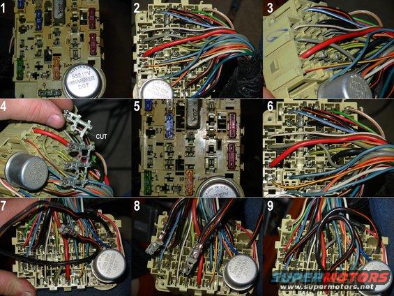
1. This is a '93 Bronco panel, so the PW hot supply is the top of position 14. This terminal needs to be isolated from its key-on supply, and then connected to an always-on supply.
2. From the back, the buss bar is visible feeding 4 of the 5 terminals on this row. Fortunately, the target is the last one, so it will be easy to isolate. If it was in the middle, a new jumper would have to be added from the original supply wire to the cut end.
3. While holding tension from the back, release the lock for each terminal on the front, and pull the buss bar out of the fuse block.
4. I was able to break this off by hand, but regular wire cutting pliers are easier. Trim away the joiner section and use picks to UNcrimp the single terminal.
5. The shortened buss bar can go back in, leaving the target socket empty.
6. Considering the relatively high current draw of the PW circuit (as much as 20A, based on the factory circuit breaker rating), I selected the hot feed coming in from PDB MAXI fuse L (50A) as being suitable. It feeds the PowerPoint socket in position #13 through this heavy Bk/Or wire.
7. The Bk/Or wire comes into the fuse panel at the unused #5 position, feeds the buss bar going to position #9, then runs on a heavy jumper wire up to position #13. Pull the jumper out of the harness to splice the #14 terminal on.
8. It's probably not necessary to remove the #13 terminal, but it might make it easier to work with. Fold the wire, ring & slice the insulation on each side of the fold, strip it, insert the fold into the opened crimp of the target terminal, and solder it. Re-crimping it isn't secure enough, and 2 layers of this heavy wire would be too much for this terminal's crimp anyway. Solder will hold forever.
9. Reinstall the terminals & fuses, and make a note in the owner's manual so you (& any future owner) can remember this mod.
This mod also makes the 1-touch mod more functional, since it can be connected to a remote system.
See also:
Is this accurate? Sign in to help verify it.
Comments
More from this build


No comments yet.