Page from a manual with diagrams and technical text.
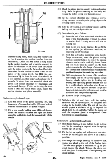
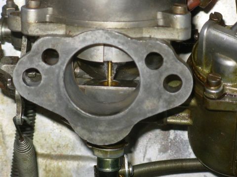
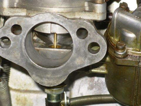
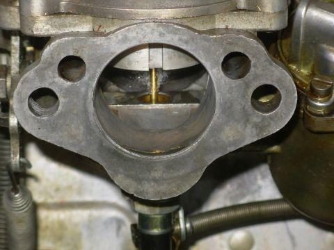
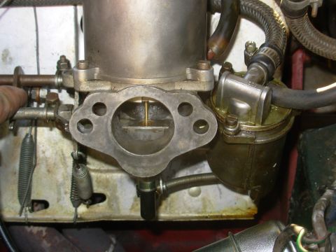
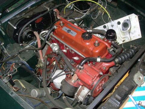
CARBURETTERS 70 DO494A chamber xing holes, positioning the washer (70) so that it overlaps the suction chamber bore (see illustration). Check that the piston is fully home in the suction chamber and invert the assembly to allow the chamber to fall away from the piston until the piston contacts the at washer. Check the time taken for the suction chamber to fall the full extent of the piston travel. For HSZtype car- buretters of 1:]: in. bore the time taken should be 3 to 5 seconds, and for larger carburetters 5 to 7 seconds. If these times are exceeded check the piston and suction chamber for cleanlinessand mechanical damage. If after rcchecking the time taken is still not within these limits. renew the suction chamber and piston assembly. Carburettersxed needle type (12) Ret the needle to the piston assembly (19). The lower edge of the needle shoulder (22) must be level with the bottom face of the piston rod (20). (13) Fit a new needle locking screw (21) and tighten. Invert the suction chamber and Spin the piston assembly inside it to check for concentricity of the needle. 4-8 424 (14) Check the piston key for security in the carburetter body. Ret the piston assembly to the body and replace the piston spring over the piston rod. (15) Fit the suction chamber and retaining screws, taking care not to wind up the spring; tighten the securing screws evenly. ( l6) Ret the jet bearing, a new locking washer, and the locking nut; do not tighten the nut. (17) Centralize the jet as follows: (a) Enter the end of the nylon feed tube into the base of the oat-chamber, without the gland or washer tted. Loosely secure with the re- taining nut. (b) Feed the jet into the jet bearing; do not t the jet nut spring, jet adjustment restrictor, or adjusting nut at this stage. (c) With the carburetter positioned with its inlet ange downwards, insert the piston loading tool into damper tube at the top of the suction chamber and screw in until fully home. Screw the tool back until the arrow, on the tool, points towards the inlet ange of the carburet- ter. The tool and carburetter must remain in this position throughout the centering operation. With the piston at the bottom of its travel (on the bridge), and the jet hard up against the jet bearing, slowly tighten the jet locking nut. During the tightening process ensure that the jet is not binding in its bearing when drawn in and out. If any tightness between the jet and bearing is detected, the jet locking nut must be slackened and the process repeated. (e) Remove the jet loading tool. (d) (18) Withdraw the jet and tube; ret the spring, restrictor and jet adjusting nut. Fit the gland and washer to the exible tube. The end of the tube should project a minimum of 1% in. beyond the gland. Ret the jet and tube. Tighten the sleeve nut until the neoprene gland is compressed. Over- tightening can cause leakage. Carburettersspring-Ioaded needle type (19) Ret the jet bearing, t and tighten the jet locking nut. No jet centering is required with the spring- loaded type jet needle. (20) Fit the jet nut spring and adjustment restrictor. Fit the jet adjusting nut and screw it up as far as possible. (21) Feed the jet into the jet bearing. Fit the sleeve nut, Washer and gland to the end of the exible tube. The tube must project a. minimum of 13; in. (48 mm.) .beyond the gland; Tighten the sleeve nut until the gland is compressed. Overtightening can cause leakage. Engine Emission. Issue 3. 16939
Comments
More from this build


No comments yet.