This document contains text and diagrams, likely from a manual or publication.
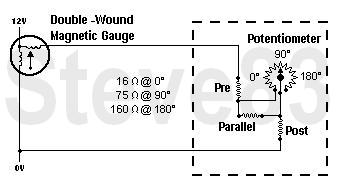
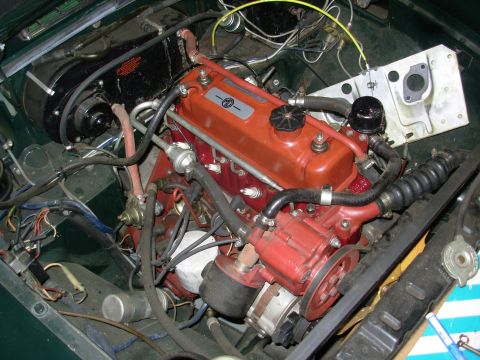
Fllelbel" 2V H A lightened. cast .irOn ywheel weighing 162- lb. (76 kg.) is now available (Part No. CAHT 86). This must be balanced with the crankshaft and clutch assembly before tting. Timing chaln sprockets With high r.p.m. and the use of high-lift camshafts the sprockets have to, withstand a. much heavier duty. The standard sprockets are cast iron, but steel sprockets for beth crankshaft and camshaft are listed on page 435. NoteMini~Cooper S camshaft sprockets do not give correct valve timing. SUSPENSION TUNING Modications to the suspension will normally affectthe handling characteri- stics of the car and give either more oversteer or understeer. These terms are recognizable as follows: ' UndersteerThe vehicle will tend to go straight on when the front wheels are turned. on lock; i.e. the slip angle of the front tyres is greater than that of the rear. OversteerThe vehicle will tend to rotate when the front wheels are turned on lock; i.e. the slip angle of the rear tyres is greater than that of the front. Factors tending towards understeer: Stiffer front springs. Fitting a front anti-roll bar, or increasing the diameter of bar. Lower front suspension (premature contact of front bump stops). Increasing rear tyre pressure above recommended gures. Decreasing front tyre pressures. MUST EQUAL AT LEAST recom- mended gures. Factors tending towards oversteer: Stiffer rear springs. Reducing size of front anti-roll bar, or tting one to rear if available. Raising front suspension (or renewing front springs if weakened). Increasing front tyre pressure above recommended gures. Decreasing rear tyre pressures. MUST EQUAL AT LEAST recom- mended gures. 6. Lowering rear suspension (premature contact of rear bump stops). P'PPPI" MPPPT Road springs Two main factors should be considered when selecting road springs for suspension tuning: (i) the stiffness of the spring, and (ii) the working load of the spring. , (i) The stiffness of the spring is expressed in lb. per inch (or kg. per cm.) which means that one inch of deection will return a load equal to the rate. Note that this rate is effective at the wheel in the case of rear non-independent axles, but is a function of the independent suspension geometry in the case of the front spring. (ii) The working load of the spring is determined by the type of use to which the car will be pt. A rally car carrying extra fuel and tyres over rough country will require a 5: 'ring with a high load capacity. For short-circuit racing a low- load capacity 5 ring will be required. It should beinoted that springs which have lost their load capacity due to settling, can p oducc the result of a lowered car. This is particularly noticeable in the case of rear springs where premature contact between the rear axle and the bump stops will produce oversteer tendencies. Road springs Fitted - Deection I height at working load (in.) Working load (1b.) Rate Par! No. (lb./in.) AHH 6451 TAHH 5789 CAHT 21 *AHH 7080 IAHH 6453 CAHH 8343 TAHC 31 AHH 7346 CAHT 20 450 (at) 400 (at) 375 (at) 510 (at) 542 (at) 542 (at) ' * Fitted to MGB Tourer from Car No. 11313. I Fitted to Tourer prior to Car No. 11313. t Fitted to MGB GT. Fitted to all MGB Tourers from Car No. 108039. Anti-roll bars H; in. (14-3 mm.) AHH 7329 (2 off bearing AHH 6541 also. required). 1% in. (15-9 mm.) CAHH 7593 (includes bearings). % in. (18 mm.) CAHH 7924 (includes bearings emit 713% '3); . Installation kit CAJJ 3306 is required if the car hasnetinrsdusl "beengtted with an anti-roll bar, and can be used with any of the ammneembm; Shock absorbers For competition work it may be desired to t shook newsman a .stiffr setting as follows: Shock absorberfront C~AHH 7104 2013 Shock absorberrear R.H. CAI-IH 7105 1 off Shock absorberrear L.H. CAHH 7106 1 off New shock absorbers can be changed from standard to sti" setting by tting valve assembly~front CAHH 7217, 2 off and valve assemblyrear CAHH 7218,.2 off. This is not advisable if any wear has taken place. Tyres and tyre pressure All testing at the works is carried out on Dunlop tyres and consequently no information is available on the effect of tting other makes of tyre. Any queries of this nature should be directed to the tyre manufacturer concerned. Advice on the use of Dunlop racing tyres and recommended pressure for competition use may be obtained from the Competition Department, Dunlop Ltd., Fort Dunlop, Erdington, Birmingham 24, England. Distributor The special distributor used in Stage 4 has no vacuum advance and has an advance curve as illustrated in Fig. 4. The Part No. is CBHA 4415 (Lucas 40943A with 32-oz. spring). The automatic advance in crankshaft degrees is 24 and with a static setting of, say, 6 crankshaft degrees B.T.D.C. gives a maximum advance of 30. Sparking plugs The standard plug was Champion N5, but is now N9Y. For competition purposes N3 is recommended, or if a colder grade of plug is required use N62R, or colder N57R. Dynamo For long-distance races it is preferable to run the dynamo at a slower speed by the tting of a suitable pulley and drive belt (see list for details, page 435). Exhaust system The twin exhaust manifold down pipes and twin silencers are very eicient but for competition purposes a lightweight steel tube free-ow manifold is available, (Part No. CAHH 7103), also the centre silencer can be removed and replaced by a section of plain pipe 2 in. (51 mm.) outside diameter and approximately -048 in. (1-2 mm.) thick. The tail pipe and rear silencer should be retained. The noise level will, of course, be increased (see FOREWORD regarding regulations). Fly-offvhand brake To convert your hand-brake to the y-o type, the following are required: Pawl . .. . . . . . . CAHH 7223 Operating rodearly cars . . . . CAHH 7222 from Car No. 115596 and all GHN/D4 cars C-AI-IC 551 Headlamp cowls (Sebring) Perspex headlamp cowls are now available as a kit set identical to those used on works cars (Part No. CAJJ 3307). Engine oil sump Especially in long-distance racing, the oil level may drop to a position where oil surge on violent cornering and braking may cause a temporary but complete loss of oil pressure. This could be seriously detrimental to the engine and may result in bearing failure. It is advisable to increase the oil capacity above the oil pump inlet and to t a bafe in the oil sump to prevent the oil surging away from the pump inlet. This can be done by tting the deep sump or altering your own sump by cutting through approximately 1% in. (31-7 mm.) from the bottom and gas welding in a l-in. (25-4 mm.) distance piece of sheet metal, or obtaining another sump and cutting off 2:1 in. (57-1 mm.) from the bottom and welding this to the top of your sump for the 18G/18GAengine. The depth should be in- creased by 1-3 in. (35 mm.) on the 18GB engine. Make up and spot-weld the surge bae to the inside of the oil sump as illustrated in Figs. 5 and 6. Larger sumps already modied are available (Part No. CAHH 7252) for 186/ 18GA engine or (Part, No. CAEH 832) for 18GB engine. Fit the correct packing piece-between the pump strainer and pump extension for 18G/ISGA (Part No. CAHH 7238) 18GB (Part No. CAEH 847), using an extra gasket and longer bolts. This will lower the oil pick-up to the correct position. Weld'iraneXtension piece onto the end of your oil dip-stick so that the original oil-levelis maintained, or use the stick as it is, and make a new maximum high- lezil-imark 1 or 11: in. (25-4 or 31-8 mm.) above the existing one. For shortwcircuits, wherepilalevels may not drop, the standard depth of sump shduid be fOund satisfactory. but the surge, baffle should be made up and tted as illustrated. 455
Comments
More from this build

No comments yet.