Home/
Registry/
Ford/
Bronco/
1992-1996/
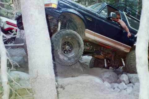
1994 Ford Bronco/
Photo
supermotors.net/registry/media/491925
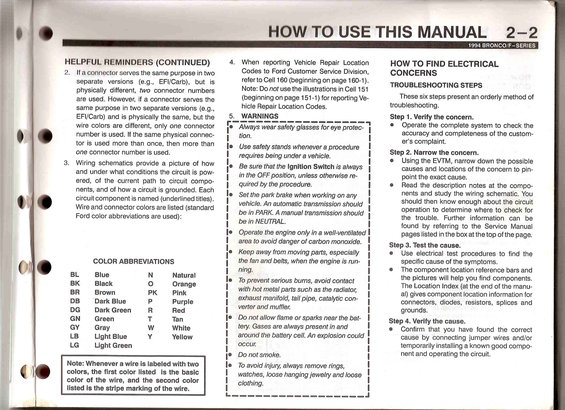
Wiring diagram details color abbreviations for vehicle wiring.
2. If a connector serves the same purpose in two separate versions (e.g., EFl/Carb), but is physically different, two connector numbers are used. However, if a connector serves the same purpose in two separate versions (e.g., EFl/Carb) and is physically the same, but the wire colors are different, only one connector number is used. lithe same physical connec- tor is used more than once, then more than one connector number is used. Wiring schematics provide a picture of how and under what conditions the circuit is pow- ered, of the current path to circuit compo- nents, and of how a circuit is grounded. Each circuit component is named (underlined titles). Wire and connector colors are listed (standard Ford color abbreviations are used): () . COLOR ABBREVIATIONS ' BL Blue N Natural BK Black 0 Orange BR Brown PK Pink DB Dark Blue P Purple DG Dark Green R Red GN Green T Tan GY Gray W White LB Light Blue Y Yellow LG Light Green Note: Whenever a wire is labeled with two colors, the first color listed is the basic color 01 the wire, and the second color listed is the stripe marking of the wire. I.___ HOW TO USE THIS MANUAL 2-2 HELPFUL REMINDERS (CONTINUED) 4. When reporting Vehicle Repair Location Codes to Ford Customer Service Division, referto Cell 160 (beginning on page 160-1). Note: Do not use the illustrations in Cell 151 (beginning on page 151-1) for reporting Ve- hicle Repair Location Codes. 5. WARNINGS I"__"'-'___-___"-_'l I. Always wear safety glasses for eye protec tion. Use safety stands whenever a procedure requires being under a vehicle. Be sure that the Ignition Switch is always in the OFF position, unless otherwise re- quired by the procedure. Set the park brake when working on any vehicle. An automatic transmission should be in PARK. A manual transmission should be in NEUTRAL. Operate the engine only in a well-ventilated area to avoid danger of carbon monoxide. Keep away from moving parts, especially the fan and belts, when the engine is run- ning. To prevent serious burns, avoid contact with hot metal parts such as the radiator, exhaust manifold, tailpipe, catalytic con- verter and muffler. Do not allow flame or sparks near the bat- tery. Gases are always present in and around the battery cell. An explosion could occur Do not smoke. To avoid injury, always remove rings, watches, loose hanging jewelry and loose clothing. ._____.___________._J HOW TO FIND ELECTRICAL CONCERNS TROUBLESHOOTING STEPS These six steps present an orderly method of troubleshooting. Step 1. Verify the concern. Operate the complete system to check the accuracy and completeness of the custom- ers complaint. Step 2. Narrow the concern. Using the EVTM, narrow down the possible causes and locations of the concern to pin- point the exact cause. Read the description notes at the compo- nents and study the wiring schematic. You should then know enough about the circuit operation to determine where to check for the trouble. Further information can be found by referring to the Service Manual pages listed in the box at thetop otthe page. Step 3. Test the cause. Use electrical test procedures to find the specific cause of the symptoms. The component location reference bars and the pictures will help you find components. The Location Index (at the end of the manu- al) gives component location information for connectors, diodes, resistors, splices and grounds. Step 4. Verify the cause. Confirm that you have found the correct cause by connecting jumper wires and/or temporarily installing a known good compo- nent and operating the circuit.
Comments
More from this build


No comments yet.