Home/
Registry/
Ford/
Bronco/
1992-1996/
1994 Ford Bronco/
Photo
supermotors.net/registry/media/491924
1994 Ford Bronco/F-Series Component Location View - Connector Locations Diagram

Reference · 1992-1996 BroncoAll 95 schematics
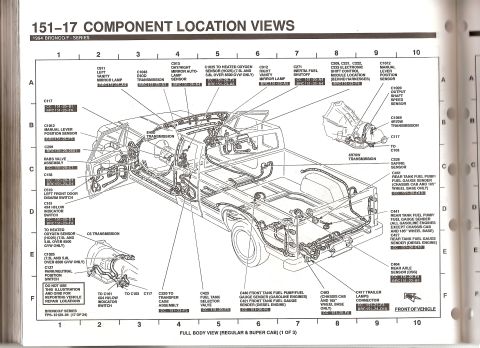

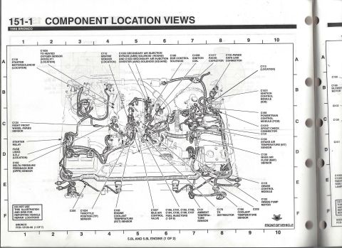
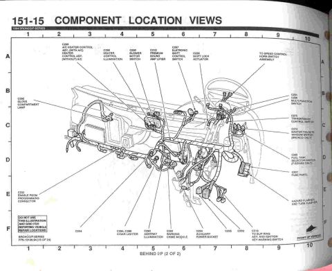








Ford 1994 Bronco/F-Series component location view showing sensor and connector positions across the full vehicle body.
Part of 1992-1996 Ford Bronco Schematics
This is page 151-17, "Component Location Views," from the 1994 Ford Bronco/F-Series electrical/vacuum troubleshooting manual (FPS-12129-94, sheet 17 of 24). It presents a full body view (regular and super cab) exploded line drawing, page 1 of 3, overlaid on a lettered/numbered grid (A-F, 1-10) showing the physical locations of electrical connectors and components throughout the truck body and driveline. Each callout identifies a connector number (e.g., C117, C271 inertia fuel shutoff, C328 safing sensor, C423 fuel tank selector valve, C440/C441 front and rear tank fuel pump/fuel gauge senders, C404 rear axle DSS sensor, C417 trailer lamps connector) along with cross-reference codes (CC and BRC page-grid references) pointing to the related wiring diagrams. Transmission-related items include the E4OD, 4R70W, and C6 transmissions, C1012 manual lever position sensor, C1020 output shaft speed sensor, C127 park/neutral position switch, and the C209/C221/C222/C223 electronic shift control module location. Several notes limit applicability by configuration, such as heated oxygen sensor connections for 7.5L and 5.8L engines over 8500 GVW, chassis-cab/185-inch-wheelbase fuel senders, and diesel-engine variants. A caution states the illustration and grid must not be used for reporting vehicle repair locations.
Is this accurate? Sign in to help verify it.
Frequently asked questions
- Where is the inertia fuel shutoff switch connector on a 1994 Ford Bronco/F-Series?
- The diagram identifies connector C271 for the inertia fuel shutoff, cross-referenced to CC 151-20-A4 and BRC 151-23-A4, located in the cab area of the full body view.
- What connector is the fuel tank selector valve on a 1994 F-Series?
- The fuel tank selector valve is connector C423, cross-referenced to CC 151-20-F5, shown under the cab in the full body view.
- Which connectors are for the front and rear tank fuel pump/fuel gauge senders?
- C440 is the front tank fuel pump/fuel gauge sender (gasoline engines) and C421 the front tank fuel gauge sender (diesel). C441 is the rear tank fuel pump/fuel gauge sender (with a separate C441 variant for chassis cab and 185" wheelbase), and C427 is the rear tank fuel gauge sender for diesel engines.
- What transmissions are shown in this component location view?
- The diagram shows the E4OD, 4R70W, and C6 transmissions, including C1048 (E4OD), C1049 (4R70W), C1012 manual lever position sensor, C1020 output shaft speed sensor, and C127 park/neutral position switch.
- What is connector C404 on the 1994 Bronco/F-Series?
- C404 is the rear axle sensor (DSS), cross-referenced to CC 151-20-F9 and BRC 151-23-A6, located at the rear axle.






No comments yet.