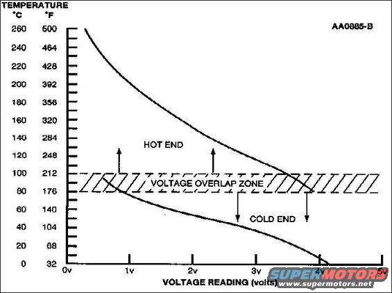
CHT Sensor Graph for switching EECs
The cylinder head temperature (CHT) sensor is a thermistor device in which resistance changes with temperature. The electrical resistance of a thermistor decreases as temperature increases, and increases as temperature decreases. The varying resistance affects the voltage drop across the sensor terminals and provides electrical signals to the PCM corresponding to temperature.
Thermistor-type sensors are considered passive sensors. A passive sensor is connected to a voltage divider network so that varying the resistance of the passive sensor causes a variation in total current flow.
Voltage that is dropped across a fixed resistor in series with the sensor resistor determines the voltage signal at the PCM. This voltage signal is equal to the reference voltage minus the voltage drop across the fixed resistor.
The cylinder head temperature (CHT) sensor is installed in the aluminum cylinder head and measures the metal temperature. The CHT sensor can provide complete engine temperature information and can be used to infer coolant temperature. If the CHT sensor conveys an overheating condition to the PCM, the PCM would then initiate a fail-safe cooling strategy based on information from the CHT sensor. A cooling system failure such as low coolant or coolant loss could cause an overheating condition. As a result, damage to major engine components could occur. Using both the CHT sensor and fail-safe cooling strategy, the PCM prevents damage by allowing air cooling of the engine and limp home capability. For additional information, refer to Powertrain Control Software for Fail-Safe Cooling Strategy details.
Fail-Safe Cooling Strategy
The fail-safe cooling strategy is activated by the PCM only in the event that an overheating condition has been identified. This strategy provides engine temperature control when the cylinder head temperature exceeds certain limits. The cylinder head temperature is measured by the Cylinder Head Temperature (CHT) sensor. For additional information about the CHT sensor, refer to PCM Inputs for a description of the CHT sensor. Note: Not all vehicles equip with a CHT sensor will have the fail-safe cooling strategy.
A cooling system failure such as low coolant or coolant loss could cause an overheating condition. As a result, damage to major engine components could occur. Along with a CHT sensor, the fail-safe cooling strategy is used to prevent damage by allowing air cooling of the engine. This strategy allows the vehicle to be driven safely for a short time with some loss of performance when an overheat condition exist.
Engine temperature is controlled by varying and alternating the number of disabled fuel injectors. This allows all cylinders to cool. When the fuel injectors are disabled, their respective cylinders work as air pumps, and this air is used to cool the cylinders. The more fuel injectors that are disabled, the cooler the engine runs, but the engine has less power.
Note: A wide open throttle (WOT) delay is incorporated if the CHT temperature is exceeded during WOT operation. At WOT, the injectors will function for a limited amount of time allowing the customer to complete a passing maneuver.
Before injectors are disabled, the fail-safe cooling strategy alerts the customer to a cooling system problem by moving the instrument cluster temperature gauge to the hot zone and a PCM DTC P1285 is set. Depending on the vehicle, other indicators, such as an audible chime or warning lamp, can be used to alert the customer of fail-safe cooling. If overheating continues, the strategy begins to disable the fuel injectors, a DTC P1299 is stored in the PCM memory, and a malfunction indicator light (MIL) (either CHECK ENGINE or SERVICE ENGINE SOON), comes on. If the overheating condition continues and a critical temperature is reached, all fuel injectors are turned off and the engine is disabled.
Note: Not all vehicles with a cylinder head temperature (CHT) sensor have the fail-safe cooling strategy. But most with ONLY an electric cooling fan motor (not those with both electric AND pulley-driven) have FSC.
Is this accurate? Sign in to help verify it.
Comments
More from this build


No comments yet.