How-to
1983 Ford Bronco Fuel Level Sender Cleaning and Repair
A fuel gauge that pegs full is usually an open circuit, and fuel varnish on the level sender's rheostat board is a common cause inside the tank. These photos follow the sender apart on the bench, through cleaning and polishing of the board, brass wipers and ground surfaces, and back together for a resistance check before it goes back in the tank.
-
Step 1
Diagnose the gauge before opening anything: a gauge pegged past full points to an open circuit on the Y/W wire, a gauge pegged past empty to a short to ground or a sunken float, and a gauge stuck in between to an open circuit on the power side or a bad cluster ground at C251 pin 9. Polish both the C251 connector pins and the film circuit pads with brown paper or a pink eraser, since those terminals are known to corrode and read high. Steve83 notes the sender can often be cleaned and returned to service for a fraction of the cost of a new one, but a new O-ring is required between the pump mounting plate and the tank either way.
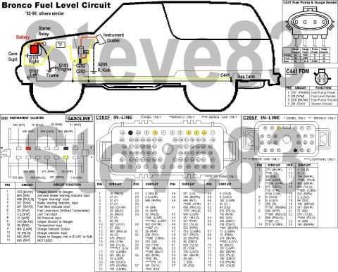
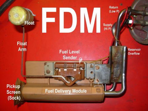
-
Step 2
With the fuel delivery module out, pry the float arm out of the sender clip between the clip and the pivot hole, taking care not to break the plastic. Use a drop of clean motor oil to ease it, which Steve83 names as the only approved lubricant inside the fuel system.
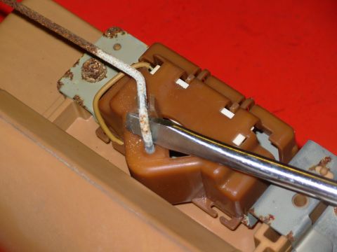
-
Step 3
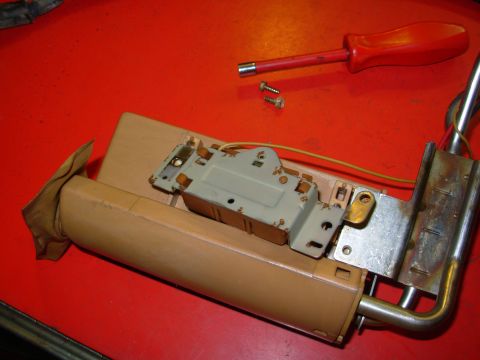
Remove the two 1/4" screws shown and the one below the sender. Leave the screw that holds the fuel delivery module to the hard lines above the sender.
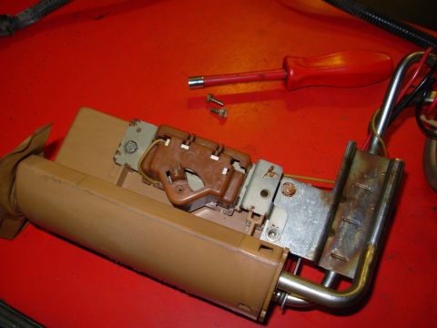
-
Step 4
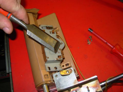
Flip the sender over for access to its clips. Cut off the melted peg or pegs.
-
Step 5
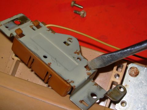
Release the catch and slide the plastic housing off the metal plate. Trim the peg that was cut off so it does not engage the plate, which makes reassembly easier.
-
Step 6
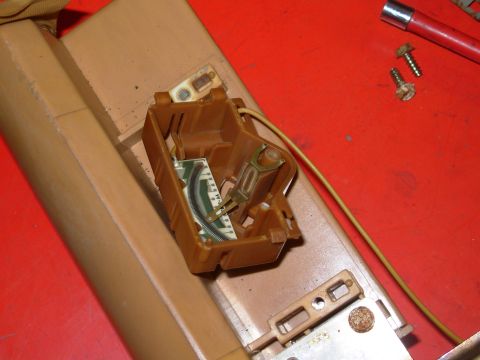
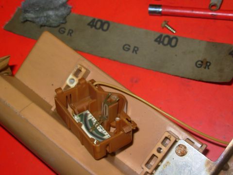
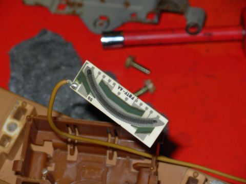
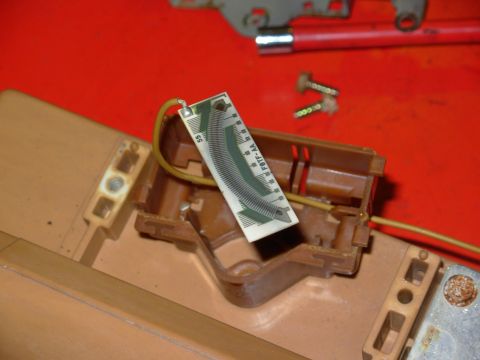
Ease out the long catches to unsnap the rheostat board from the housing, noting that the wiper arm is loose inside once the float arm is off. Feed the Y wire through as the board comes out so it is not ripped off, and solder it back on if it breaks free.
-
Step 7
Steve83 cleans the board with #000 steel wool and the brass wiper contacts with 400 grit emery paper, then gently bends the polished brass so it applies slightly more force to the board and to the stainless mounting plate that grounds it. Leave the green areas alone, since they provide the necessary resistance and cleaning can permanently change it.
-
Step 8
Compare the board before and after, using the before photo from the previous step and the after photo here: most of the black corrosion between the traces should be gone. Replace the sender if the traces are damaged or corroded, and note that Steve83 reports about half the senders cleaned this way have worked afterward.
-
Step 9
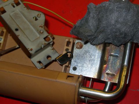
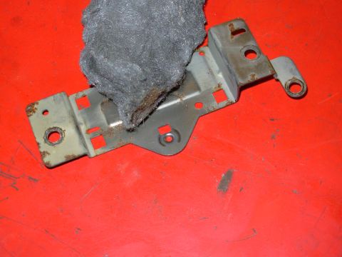
Polish the mating surfaces between the hard tubes' plate, still screwed to the fuel delivery module, and the sender backing plate so the sender has a good ground path. Polish the area around the float arm pivot hole where the brass wipers will touch.
-
Step 10
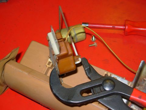
Reassemble the rheostat board, sender housing, wiper arm and backing plate, then press the float arm back into the wiper clip. Align the rod with the hole in the plate before forcing it into the clip, and lubricate the clip with clean motor oil if needed, never with silicone grease.
-
Step 11
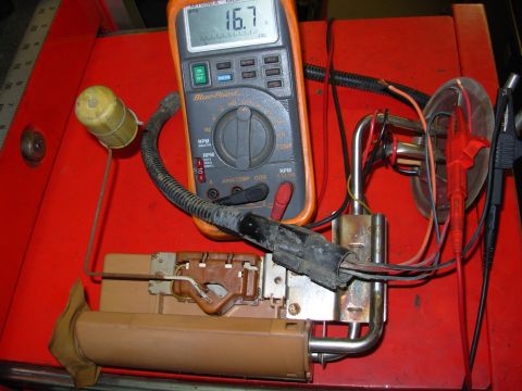
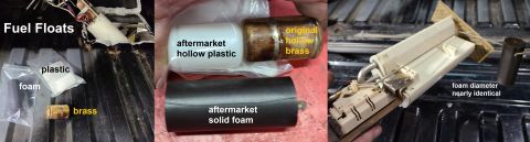
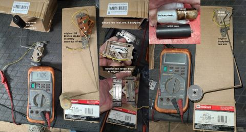
Check the sender's output across the full range and confirm it produces a smooth continuous signal from about 16 to 160 Ohms, replacing it if it does not. Inspect the hollow brass float used on Broncos and front tanks, and replace it if fuel can be heard splashing inside or it stays wet; Steve83 tests for leaks by freezing the float for about 5 minutes, submerging it in hot water to find the bubbles, and soldering the leaks shut with an electronics soldering iron and rosin-core solder.
-
Step 12
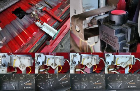
If the sender itself is beyond cleaning, swap an imported '87-04 level sender onto the existing tank hanger using the existing arm and float, bending the float arm slightly to suit the included solid foam float. The first photo shows the new sender body being moved onto the original backplate, with the new float, arm and backplate set aside. Before re-installing the sender in the tank, test gauge response in at least 3 positions, 5 being better, and allow a few minutes at each one because the gauge is built not to move rapidly. The last photo shows the sender connected to the instrument cluster, with the float arm in four positions and the needle in each. The album's photos end at this gauge test and do not cover re-installing the module in the tank.
Some product links go to the supplier the owner bought from. SuperMotors does not earn a commission today; if that changes, this line will say so and creators will be paid from it.