How-to
1989 Ford Bronco Electric Cooling Fan Install With Controller
An engine-driven fan on a 1989 Ford Bronco is replaced with a junkyard Ford electric fan run by an Imperial/Hayden fan controller. The album covers sourcing and measuring donor fans, trimming the shroud for clearance, wiring the controller and solenoid, and a later move to dual Taurus fans.
-
Step 1
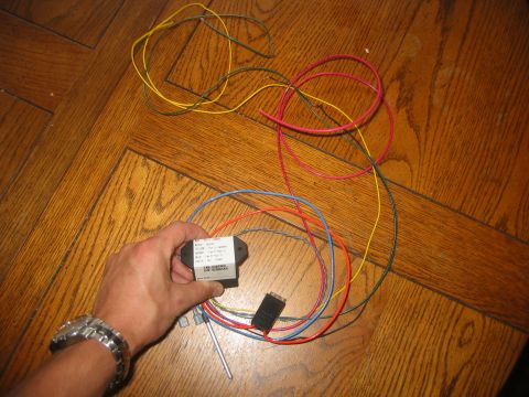
Select the fan controller for the swap. Will H used an Advance Auto Parts Imperial/Hayden controller, part # 226204.
-
Step 2
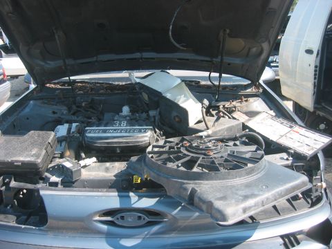
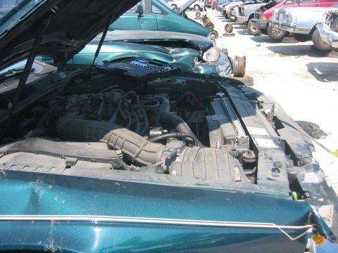
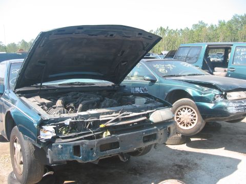
Walk the Ford rows at a salvage yard to find a donor fan. Will H set out to pull a Mark VIII fan, found a 3.8 liter Taurus fan already removed, and also pulled the fan from a 1998 Thunderbird with the 3.8 liter engine rather than the 1994 Thunderbird beside it, which had 30k more miles.
-
Step 3
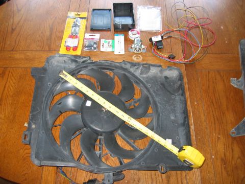
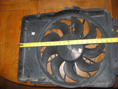
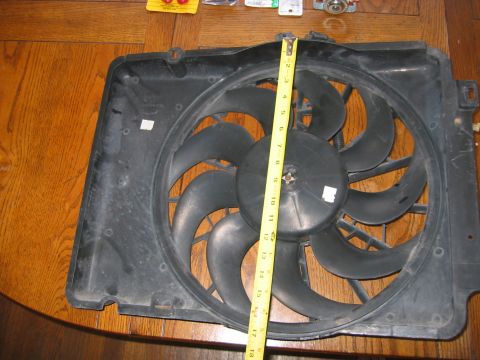
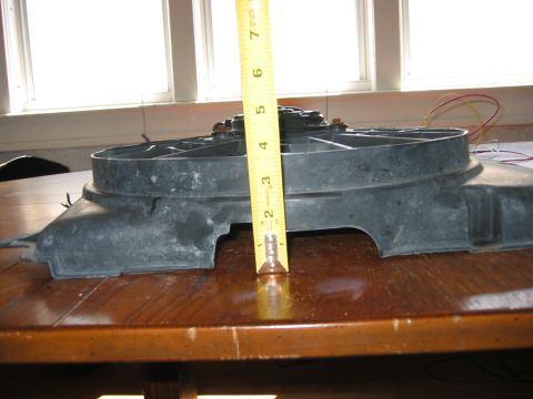
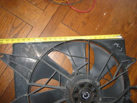
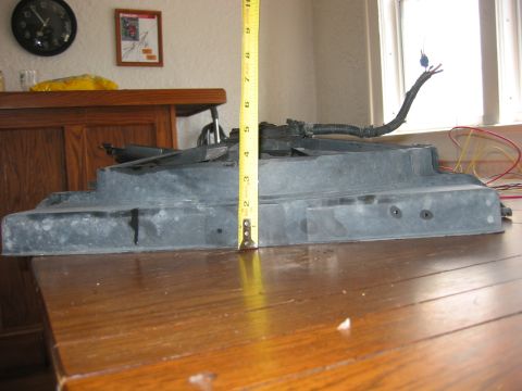
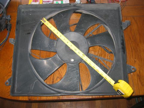
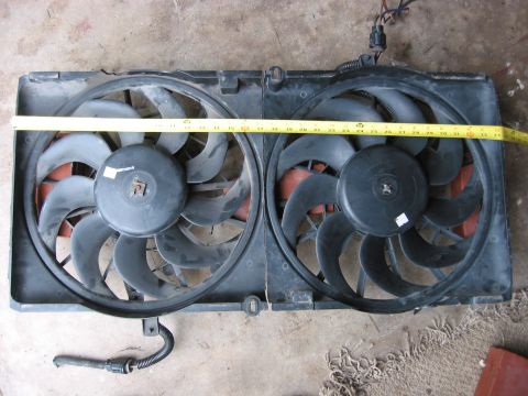
Measure each donor fan before committing to one. Will H recorded the Taurus fan and the Thunderbird fan at about 5 inches deep each. The width figures in the captions do not agree with each other, so check your own fan before relying on any number.
-
Step 4
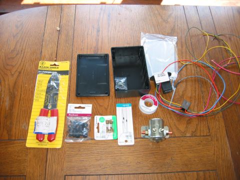
Gather the remaining parts before starting the install. Will H assembled wire cutters/strippers/crimpers, a project box, grommets, solder, fuses, diodes, a 300 amp continuous duty relay and the fan controller.
-
Step 5
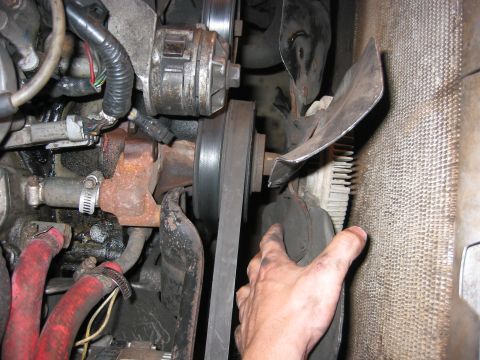
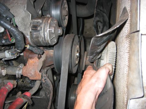
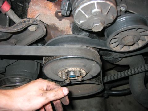
Remove the 4 bolts holding the engine-driven fan and pull the fan off, persuading it loose if it has been in place a long time. Thread the fan bolts back in, since they also hold the outer water pump pulley on.
-
Step 6
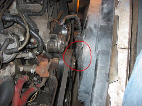
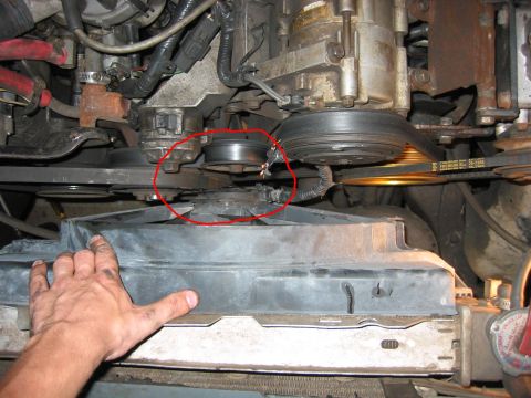
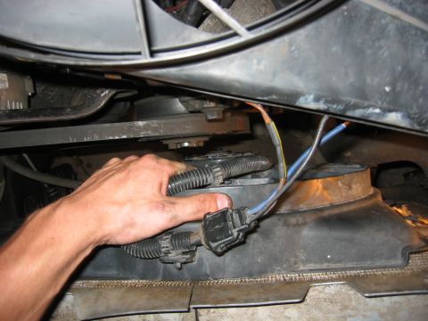
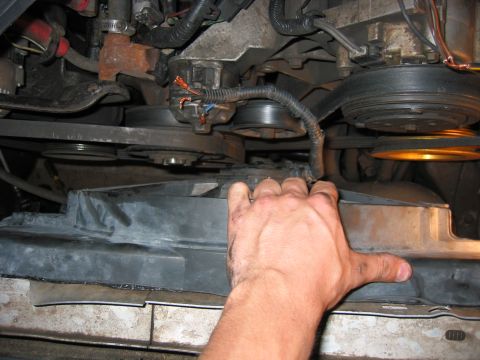
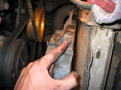
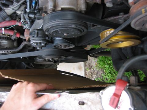
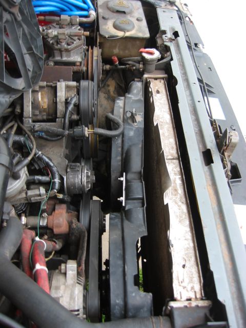
Test fit each electric fan against the radiator before cutting or mounting anything. Will H found the Thunderbird fan sat too deep, leaving only 1-2 mm between the fan motor and the pulleys, while the Taurus fan fit with room to spare.
-
Step 7
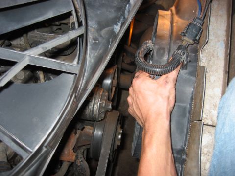
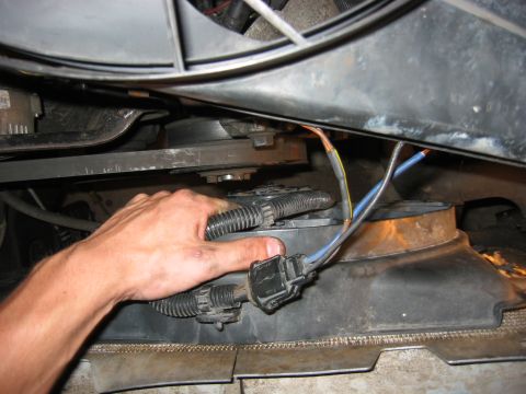
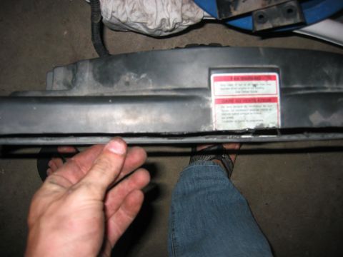
Hold the fan at different points on the radiator to choose a position; Will H found clearance both offset to the driver's side and centered. To use the larger Thunderbird fan instead, Will H cut about a half inch from the shroud, which had about 1 inch between the fan and the shroud edges, and cut off the side mounting tab so that side of the fan sat closer to the radiator and further from the engine.
-
Step 8
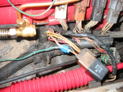
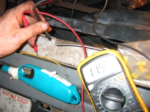
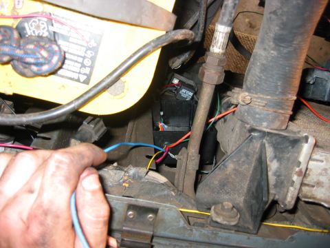
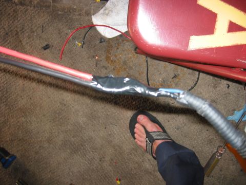
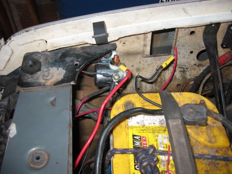
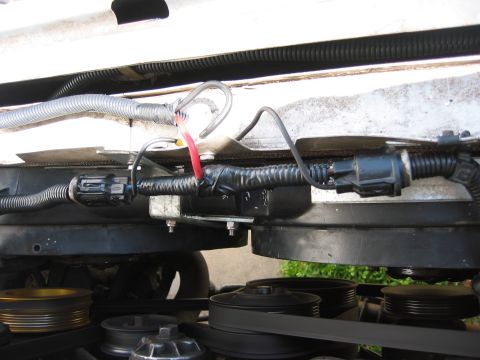
Tie the yellow controller wire into the blue/white ignition-on wire by the fuel pump/EEC relay and confirm 12V at the meter with the key on. Mount the project box, splice into the fan connector pigtail, and wire in the 300 amp continuous duty solenoid; Will H left the box open for tweaking and notes the fan draws about 33 amps, so the controller's built-in 40 amp fuse would likely have been enough.
-
Step 9
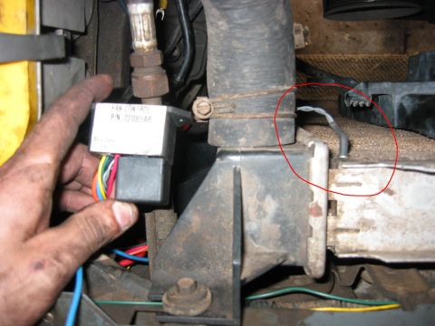
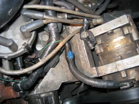
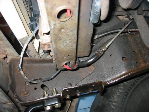
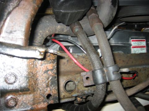
Install the temperature probe in the radiator next to the inlet coolant hose, and tie the controller's green AC ON wire in so the fan runs whenever the AC compressor engages. Route the fan wiring along the underside of the engine bay; Will H planned to add split hose over it later.
-
Step 10
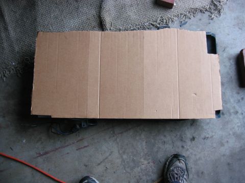
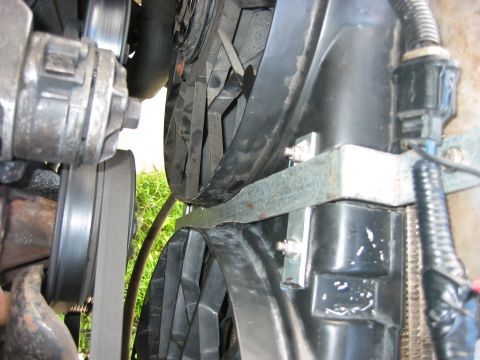
To run dual Taurus fans, cut the shrouds to clear the radiator hoses using a cardboard template laid over the fans, then test fit and trim repeatedly; Will H spent about an hour on this and ended up with the pair measuring 34.5 inches end to end. Will H retained the assembly with a 1 inch wide piece of aluminum bent to the shroud contours, tucked into the lip in the bottom of the core support and held by one bolt at the radiator lip, and considered both that bracket and the wiring as not yet final. The photos end here, with the wiring and bracket not final.
Some product links go to the supplier the owner bought from. SuperMotors does not earn a commission today; if that changes, this line will say so and creators will be paid from it.