Home/
Registry/
Ford/
Pinto/
1971-1980/
“bronco/pinto”/
Photo
supermotors.net/registry/media/1032522
Ford Remote Starter Solenoid Wiring Schematic - S & I Terminals, Coil Bypass
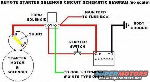
Reference · 1971-1980 PintoAll 1 schematics
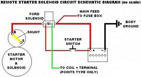
Remote starter solenoid wiring schematic showing the Ford solenoid (S/I/B terminals), main feed to fuse box, starter switch, starter motor and solenoid, body ground and coil + terminal feed for points-type ignition.
Part of 1971-1980 Ford Pinto Schematics
This document is a hand-drawn circuit schematic (marked "no scale") showing how to wire a remote Ford starter solenoid into a starter circuit. It depicts a Ford solenoid with terminals labeled S and I, a battery with + and - terminals, a body ground from the battery negative terminal, and a main feed running from the solenoid's battery-side stud to the fuse box. The starter motor with its integral solenoid is shown at lower left with B and S terminals and a shunt indicated between them. A starter switch is placed in the circuit between the Ford solenoid's S terminal and the battery positive feed. A green wire from the solenoid's I terminal is labeled "TO COIL + TERMINAL (POINTS TYPE ONLY)," indicating the ignition-bypass connection used only on points-type ignition systems. Wire routing is shown in red for main power feeds, black for ground, and green for the coil bypass wire. A reader can learn how to add a remote Ford-style starter solenoid to a starter that has its own integral solenoid, including where to connect the shunt/jumper on the starter, where the fuse box feed and coil bypass attach, and how the starter switch triggers the S terminal.
Is this accurate? Sign in to help verify it.
Frequently asked questions
- What do the S and I terminals on the Ford solenoid connect to?
- Per the diagram, the S terminal is fed through the starter switch, and the I terminal connects via a wire labeled 'TO COIL + TERMINAL (POINTS TYPE ONLY)'.
- Is the I terminal wire needed on all ignition systems?
- No. The diagram labels the I terminal wire 'TO COIL + TERMINAL (POINTS TYPE ONLY)', so it applies only to points-type ignition.
- Where does the main power feed to the fuse box come from?
- The 'MAIN FEED TO FUSE BOX' is shown coming off the battery-side large terminal of the Ford solenoid.
- What is the shunt shown on the starter?
- The diagram shows a shunt (jumper) between the B and S terminals on the starter motor & solenoid assembly.
- How is the battery grounded in this schematic?
- The battery negative terminal is connected to a body ground.


No comments yet.