Ford Power Transfer Unit Exploded Parts Diagram - 7H426, 7H459, 7H469 Callouts
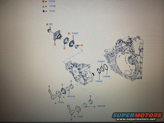
Exploded parts diagram of a transmission/PTU assembly with part-number callouts and a fastener color legend.
Part of 2007-2014 Ford Edge Exploded Parts Diagrams
This document is an exploded parts diagram (parts catalog illustration) showing a power transfer unit / transfer case assembly and its mounting relationship to a transaxle/transmission housing. A legend at the top defines three fastener/hardware symbols: an orange square = part 7275A, a green triangle = part 7275B, and a brown circle = part 7275C; these symbols are repeated throughout the drawing at bolt/fastener locations. Labeled components include a companion flange assembly with nut HN1 and seal/bearing group 7H426 at the upper left, seal/snap-ring components 7H469A and 7H469B where the unit meets the transmission case, and two lower bracket/link assemblies each labeled 7H459 with associated washer/spacer parts marked <600A58. The large housing on the right is the transmission/transaxle case to which the transfer unit mounts. A reader can learn the base part number callouts for the output flange nut, seals, mounting brackets, and the three fastener types (7275A/B/C) used to attach the assembly, along with their approximate positions on the assembly. No year, model, torque values, or textual notes appear in the image beyond the part callouts.
Is this accurate? Sign in to help verify it.
Frequently asked questions
- What do the square, triangle, and circle symbols mean on this diagram?
- The legend defines them as fasteners: square = 7275A, triangle = 7275B, circle = 7275C.
- What part number is shown for the seals at the transmission case interface?
- The diagram labels 7H469A (shown twice) and 7H469B at the joint between the transfer unit and the transmission housing.
- What is the part number for the flange nut on the output flange?
- The nut on the companion flange at the upper left is labeled HN1.
- Which callouts identify the lower bracket/link assemblies?
- Two assemblies at the bottom are labeled 7H459, each with adjacent parts marked <600A58.
- What part number covers the seal/bearing group behind the output flange?
- The group of seal/bearing components behind the flange is labeled 7H426.
Comments
More from this build
No comments yet.