Home/
Registry/
Ford/
Model T/
1908-1927/
“Centennial”/
Photo
supermotors.net/registry/media/1051116
Gray & Davis Early Generator Governor & Friction Clutch - Manual Page Figs 15-15B
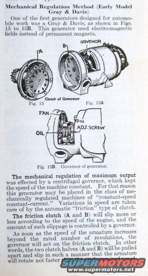
Manual page on early Gray & Davis generator mechanical regulation with exploded figures of the generator clutch and governor.
Part of 1908-1927 Ford Model T Manual Pages
This scanned page from an early automotive reference manual explains the mechanical regulation method used by early-model Gray & Davis generators, among the first generators designed for automobile use. Unlike magneto-type devices with permanent magnets, this generator used electro-magnetic fields. Three illustrations (Figs. 15, 15A, and 15B) show the clutch of the generator with parts labeled A and B, the governor assembly, and a cutaway of the governor showing the fan, oil points, and adjusting screw. The text explains that maximum output was regulated mechanically by a centrifugal governor that kept machine speed constant, classifying the generator as a "constant-speed constant-current" mechanically regulated machine. Speed variations from the engine were absorbed by an automatic friction-type clutch: the two clutch halves (A and B) slip more or less depending on engine speed, with the amount of slippage controlled by the governor. Once armature speed exceeds the rated number of revolutions, the governor pulls the clutch halves apart, causing them to slip so the armature never rotates faster than the predetermined speed. Readers can learn the operating principle of this early generator regulation system and identify its clutch and governor components from the labeled figures.
Is this accurate? Sign in to help verify it.
Frequently asked questions
- How did the early Gray & Davis generator regulate its maximum output?
- Mechanical regulation was effected by a centrifugal governor that kept the speed of the machine constant, making it a mechanically regulated "constant-speed constant-current" machine.
- What handles engine speed variations in the Gray & Davis generator?
- Variations in speed are taken care of by an automatic "friction" type of clutch, whose two halves (A and B) slip more or less according to engine speed, with slippage controlled by the governor.
- What happens when the armature exceeds its rated speed?
- The governor acts on the friction clutch, pulling the two clutch halves (A and B) apart so they slip, ensuring the armature rotates no faster than the predetermined speed.
- How does the Gray & Davis generator differ from permanent-magnet designs?
- This generator, one of the first designed for automobile work, used electro-magnetic fields instead of permanent magnets.
- What components are shown in Fig. 15B?
- Fig. 15B shows the governor of the generator, with labels for the fan, oil points, and the adjusting screw (ADJ. SCREW).
Comments
More from this build
No comments yet.