Home/
Registry/
Ford/
Model T/
1908-1927/
“Centennial”/
Photo
supermotors.net/registry/media/1152253
Schrader No. 777 Inner-Tube Tire Valve Stem Diagram - Ford Model T Era Manual
Reference · 1908-1927 Model TAll 5 manual pages
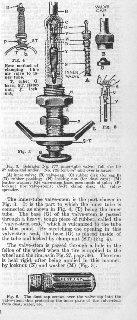
Manual page describing inner-tube valve stems with sectioned figures of a Schrader valve, valve cap, and dust cap.
Part of 1908-1927 Ford Model T Manual Pages
This is a scanned page from an early automotive reference manual (likely Dyke's Encyclopedia, based on companion scans) explaining the construction and installation of the Schrader inner-tube tire valve, as used on early automobiles such as the Ford Model T. It shows detailed cutaway illustrations: Fig. 3 depicts the Schrader No. 777 inner-tube valve (full size for 3-inch tubes and under; the No. 725 is used for 3½-inch tubes and over), with a lettered legend identifying the inner valve (A), valve-cap (B), rubber disk (C), rubber packing (D), locking nut (N), leather washer (M), valve-stem base (G), locknut (P), clamp disk (S-T), and valve-spreader (L). Fig. 4 shows how the air valve is clamped to the inner tube, Fig. 5 shows the inner valve, and Fig. 6 shows the Schrader Universal dust cap that screws over the valve-cap to protect internal parts from dust and water. The text explains that the valve-stem base passes through a vulcanized rubber "valve-stem seat," is locked with clamp nut (ST), and the stem passes through a hole in the wheel felloe, secured by locknut (N) and washer (M). The page also begins a discussion of tire tread types (smooth, non-skid, etc.). Some upper-page text is obscured by ink bleed-through.
Is this accurate? Sign in to help verify it.
Frequently asked questions
- What Schrader valve number is used for 3-inch tubes and under?
- The Schrader No. 777 inner-tube valve is shown full size for 3" tubes and under; the No. 725 for 3½" and over is larger.
- What do the letters in the Schrader valve diagram mean?
- (A) inner valve; (B) valve-cap; (C) rubber disk for cap B; (D) rubber packing; (N) locking nut for dust cap; (M) leather washer; (G) valve-stem base, which goes inside of tube; (P) locknut for valve-stem; (S-T) clamp disk; (L) valve-spreader.
- How is the valve-stem attached to the inner tube?
- The base (G) of the valve-stem is passed through a heavy, tough piece of rubber called the 'valve-stem seat,' which is vulcanized to the tube. By stretching the opening in this seat, the base (G) is placed inside the tube and locked by clamp nut (ST), as shown in Fig. 4.
- How is the valve-stem secured to the wheel?
- The valve-stem is passed through a hole in the felloe of the wheel when the tire is applied, and it is held rigid by locknut (N) and washer (M).
- What does the dust cap do?
- The dust cap screws over the valve-cap into the valve-stem, protecting the inner parts of the valve-stem from dust, water, etc. (Fig. 6).

No comments yet.