Home/
Registry/
Ford/
Torino/
1968-1969/
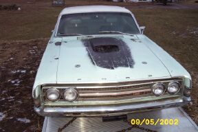
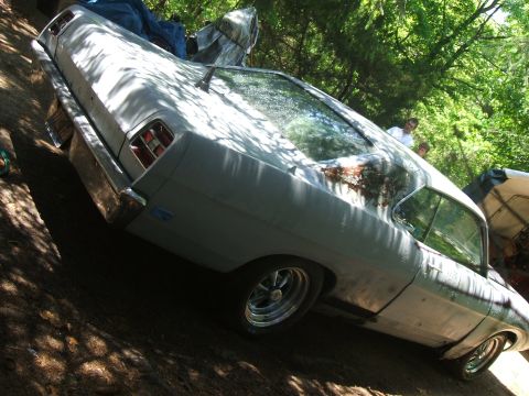
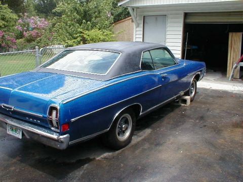
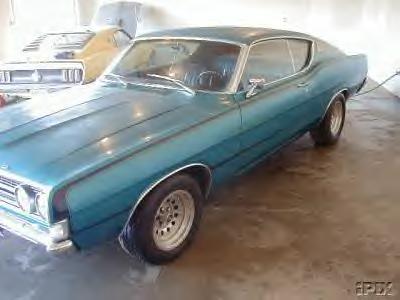
1969 Ford Torino/
Photo
supermotors.net/registry/media/1055500
Autoquip Series 35 Lift Electrical Schematic 115V 1Ph - Drawing 65750500
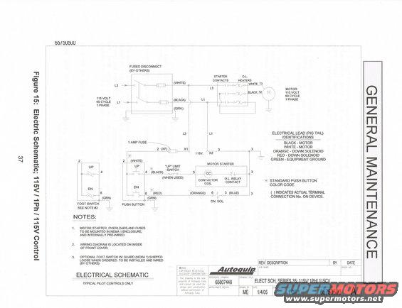
Electrical control schematic (115V/1Ph/60 cycle) for an Autoquip lift, showing fused disconnect, motor starter, contactor coil, foot/limit switches and pig-tail color code; not an automotive wiring diagram.
This document is page 37 of an Autoquip Corporation "General Maintenance" manual, showing Figure 15: an electrical schematic for a Series 35 lift with 115V / 1-phase power and 115V control (drawing number 65750500, reference drawing 65807448, drawn by ME on 1/4/05, ©2006 Autoquip). The schematic depicts a fused disconnect (supplied by others) feeding a 115-volt, 60-cycle, single-phase motor through starter contacts and overload (O.L.) heaters, with motor leads identified as WHITE T3 and BLACK T2. A 1-amp control fuse (position 2/XF) feeds the 115V control circuit (X1/X2). Controls include UP/DN push buttons (terminals 2, 4, 6), an optional foot switch, an optional "UP" limit switch, a motor starter with contactor coil (CC) and O.L. relay contact, and a down solenoid (DN. SOL.). A legend identifies pig-tail lead colors: black and white for motor, orange and red for down solenoid, green for equipment ground. Notes state the motor starter, overloads, and fuses are mounted in a NEMA 1 enclosure and pre-wired; the wiring diagram is inside the front cover; and the optional foot switch ships loose for installation by others. This is lift equipment documentation, not vehicle wiring.
Is this accurate? Sign in to help verify it.
Frequently asked questions
- What voltage and phase does the Autoquip Series 35 lift schematic show?
- 115 volt, 60 cycle, 1 phase power with 115V control, fed through a fused disconnect supplied by others.
- What size is the control circuit fuse in this schematic?
- A 1 amp fuse (marked 2 (XF)) protects the 115V control circuit between X1 and X2.
- What do the pig tail wire colors mean on this lift?
- Black - motor, White - motor, Orange - down solenoid, Red - down solenoid, Green - equipment ground.
- Where is the wiring diagram located per the notes?
- Note 2 states the wiring diagram is located on the inside of the front cover.
- How is the optional foot switch supplied?
- Per Note 3, the optional foot switch with guard (NEMA 1) is shipped loose when ordered and is to be installed and wired by others.
Comments
More from this build
No comments yet.