Home/
Registry/
Triumph/
Executive/
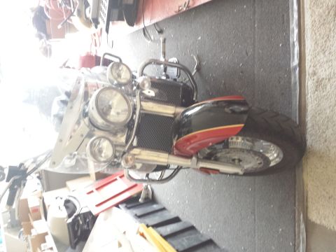
“Rocket 3 Bramma Momma”/
Photo
supermotors.net/registry/media/1092166
2014 Triumph Trophy Executive Clutch Exploded Parts Diagram - Items 1-26
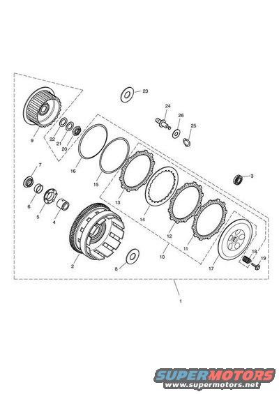
Exploded parts breakdown of a clutch assembly showing basket, plates, and hardware with numbered callouts.
This document is an exploded parts diagram, apparently of a motorcycle clutch assembly, uploaded to the gallery of a 2014 Triumph Executive. The line drawing shows the clutch components separated along their axis of assembly, with numbered callouts 1 through 26 identifying individual parts. Visible components include a large finned clutch outer basket/drum with gear teeth (item 2), a geared drum or sprocket (item 9), an alternating stack of toothed friction plates and plain steel plates (items 11-14, grouped as item 10), large retaining rings (items 15 and 16), a pressure plate with circular lightening holes (item 17), a splined hub and sleeve (items 4 and 5), various washers, seals, and rings (items 6, 7, 8, 20, 21, 22, 23, 26), a pushrod or actuator pin (item 24), a clip (item 25), and a bolt with spring/washer (items 18 and 19). Item 1 denotes the complete assembly, indicated by the dashed boundary around the drawing. The document contains no legend, part numbers, text labels, torque specifications, or year/model identification, only the callout numbers. A reader can learn the assembly order and relative positions of the clutch components, but must cross-reference the callout numbers with a separate parts list to identify part numbers.
Is this accurate? Sign in to help verify it.
Frequently asked questions
- What does this diagram show?
- An exploded view of a clutch assembly with 26 numbered callouts, showing the clutch basket, hub, friction and steel plate stack, pressure plate, retaining rings, washers, pushrod, and fasteners in their assembly order.
- How many friction/steel plates are shown in the plate stack?
- The dashed sub-group (item 10) shows four plates in the exploded stack, toothed friction plates (items 11, 12, 13) and a plain plate (item 14).
- Does the diagram include part numbers or torque values?
- No. Only callout numbers 1 through 26 are shown; there is no legend, part number list, or torque specification in the image.
- What does callout 1 refer to?
- Callout 1 points to the dashed boundary enclosing the entire exploded view, indicating the complete clutch assembly.
- Which item is the pressure plate?
- Item 17 is the plate with circular openings at the lower right of the diagram, secured by the bolt (19) and spring/washer (18).
Comments
More from this build
No comments yet.