GM HEI Module Wiring Pinout for Mazda Ignition Swap - Pins W, G, B, C Diagram
Reference · 1993-1997 626All 1 wiring diagrams
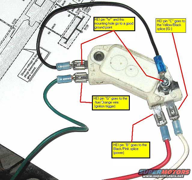
HEI ignition module photo annotated as a wiring guide, labeling pins W, C, G and B and their wire connections.
Part of 1993-1997 Mazda 626 Wiring Diagrams
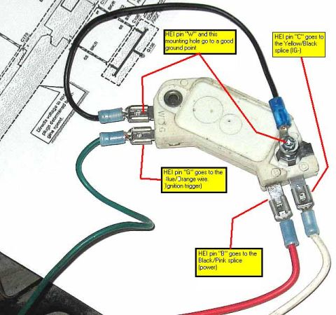
This is an annotated photograph (not a traditional schematic) showing how to wire a GM-style 4-pin HEI ignition control module for an ignition conversion/retrofit. The white HEI module is shown with blue crimp-on female spade connectors attached to its four terminals, and yellow callout boxes with red leader lines identify each connection: pin "W" (along with the module mounting hole) goes to a good ground point; pin "C" goes to the Yellow/Black splice (IG-); pin "G" goes to the Blue/Orange wire, which is the ignition trigger; and pin "B" goes to the Black/Pink splice for power. The wire colors visible in the photo include black (ground), green, red, and white leads. The module sits on top of a printed factory wiring diagram page, of which only fragments are legible, including a note that reads approximately "Directs voltage to spark plugs determined by engine speed." A reader can learn the exact pin-to-wire mapping needed to install this HEI module into a vehicle harness that uses Yellow/Black (IG-), Blue/Orange (trigger), and Black/Pink (power) wire splices, colors consistent with a Mazda ignition circuit, matching the uploader's 1995 Mazda 626 attribution, though the document itself states no year or model.
Is this accurate? Sign in to help verify it.
Frequently asked questions
- Where does HEI module pin "W" connect?
- Pin "W" and the module mounting hole both go to a good ground point.
- Which wire is the ignition trigger for the HEI module?
- Pin "G" goes to the Blue/Orange wire, which is the ignition trigger.
- Where does the HEI module get power?
- Pin "B" goes to the Black/Pink splice, which is the power connection.
- What does HEI pin "C" connect to?
- Pin "C" goes to the Yellow/Black splice, labeled IG- (the negative ignition/tach side).
- How are the wires attached to the HEI module?
- The photo shows blue insulated crimp-on female spade connectors attached to the module's four spade terminals.


No comments yet.