This document details the removal and installation process for a clutch cable and its adjustment mechanism.
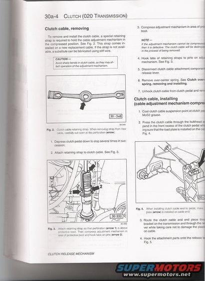
30a-4 CLUTCH (020 TRANSMISSION) Clutch cable, removing To remove and install the clutch cable, a special retaining strap is required to hold the cable adjustment mechanism in the compressed position. See Fig. 2. This strap comes in- stalled on a new replacement cable. if the strap is not avail- able. a substitute can be fabricated using stiff wire. CA U TION Avoid sharp bends in clutch cable. as they may af- fect operation of the adjustment mechanism. t 307345 Fig. 2. Clutch cable retaining strap. When removing strap from new cable. carefully cut open at the perforation (arrow). 1. Depress clutch pedal down to stop several times in suc cession. 2. Attach retaining strap to clutch cable. See Fig. 3. Fig. 3. Attach retaining strap so that perforation (arrow 1) is above protective boot. Then compress adjustment mechanism in area of protective boot and hook tabs on pins (arrow 2). CLUTCH RELEASE MECHANISM i t: 3. Compress adjustment mechanism in area of p# boot. . ,1 NOTE - If the adjustment mechanism cannot be comp/es then it is defective. The clutch cable will be desfro in the process of being removed. 4. Hook tabs of retaining straps to pins on adjii mechanism. See Fig. 3. i i 5. Disconnect clutch cable attachment componeri release lever. t 6. Remove over-center spring. See Clutch overi spring, removing and installing. i 7. Unhook clutch cable from clutch pedal and red r Clutch cable, installing (cable adjustment mechanism comprei 1. Coat clutch cable suspension point at clutch H M082 grease. 2. Press the clutch cable through the bulkhead q pend in the front recess of the clutch pedal :1: ing sure that the load plate is installed on the Fig. 4. l Fig. 4. When installing clutch cable end to pedal, makei plate (arrow) is installed on cable end. ' t A 3. Route the clutch cable and end piece thrd bracket on the transmission and through the rd ver while taking care not to damage the plasd on cable. 4. Hook the attachment parts onto the release id Fig. 5.
Comments
More from this build


No comments yet.