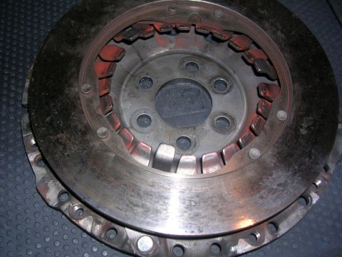
This document page illustrates the clutch cable adjustment mechanism and its functional check.
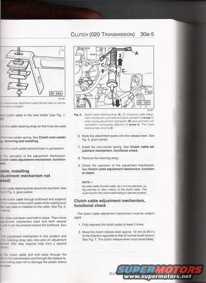
7 CLUTCFl (020 TRANSMISSION) 30a5 30-345 ase lever attachment parts (shown here on vehicle ce weight). e: clutch cable in the wire holder (see Fig. 1, 26 the cable retaining strap so that it can be used Te overcenter spring. See Clutch over-center lg. removing and installing. as :he clutch pedal several times in succession. tr :'e operation of the adjustment mechanism. Llutch cable adjustment mechanism, function- eck :able, installing djustment mechanism not ssed) 2 cable retaining strap above the dust boot. See . - _. Fig. 3, given earlier. 307351 Fig. 6. Clutch cable retaining strap (A). To compress cable adjust ment mechanism, pull cable end down (direction of arrow 1). while moving adjustment mechanism (B) back and forth until mechanism compresses (direction of arrow 2). Then hook retaining tabs on pins (C). 6. Hook the attachment parts onto the release lever. See Fig. 5, given earlier. 7. install the over-center spring. See Clutch cable ad- justment mechanism, functional check. 8. Remove the retaining strap, 9. Check the operation of the adjustment mechanism. See Clutch cable adjustment mechanism, function- al check. NOTE No other cable (throttle cable, etc.) is to be attached, us- ing wire-ties or other means, to the clutch cable. This could result in the clutch cable falling to operate properly. 5 Te clutch cable through bulkhead and suspend _ ": recess of the clutch pedal while making sure :ad plate is installed on the cable. See Fig. 4, ' .er. Clutch cable adjustment mechanism, functional check The clutch cable adjustment mechanism must be undam- re sable end down and hold in place. Then move aged. 3: :ment mechanism back and forth several : it can be pressed toward the bulkhead. See 1. Fully depress the clutch pedal at least 5 times. 2. Move the clutch release lever approx. 10 mm (0.39 in.) in the direction opposite to that of normal travel (down). :e adjustment mechanism in this position and - See Fig. 7. The clutch release lever must move freely. staining strap tabs onto pins on adjustment S'Tl (this step requires help from a second : Te clutch cable and end piece through the the transmission and through the release le- aking care not to damage the plastic sleeve CLUTCH RELEASE MECHANISM
Comments
More from this build


No comments yet.