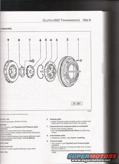
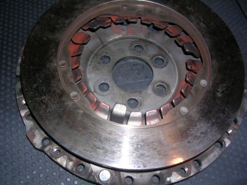
Diagram shows an exploded view of a clutch assembly with numbered components and accompanying text detailing installation and specifications.
I assembly CLUTCH7(020 TRANSMissiou) 30a-9 L" : :ed view of clutch and related parts. an M7 x 40 gntening torque: 20 Nm (15 ft-lb) Wheel The yersions, see Flywheel and Pressure plate versions 5(8 sure that dowel pin(s) seat properly C etch lining friction surface must be free of grooves, c and grease E erent clutch/flywheel sizes require different clutch t"casing (timin mark plugs. See 34 Manual 9 lransmission Iutch disc Dutch push rod G'ease in area of guide bushing in input shaft map ring 30382 Release plate - Lightly lubricate pressure plate contact surface and clutch pushrod socket with G 000 100 grease Attachment bolt, pressure plate to crankshaft - Stretch boltalways replace - See 13 Crankshaft/Cylinder Block for tightening torque Intermediate plate - Installation position, see Clutch, installing, Pressure plate - Two versions, see Flywheel and Pressure plate versrons - Maximum distortion of pressure plate inner surface: 0.2 mm (0.008 in.) - Replace pressure plate that has damaged or loose rivets. CLUTCH
Comments
More from this build


No comments yet.