The diagnostic communication network:
> consists of a single wire, Circuit 70 (LB/W).
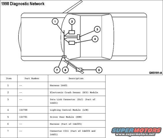
> provides a common link for communication to an off-board tester through the data link connector (DLC) located under the instrument panel (04320) to the right of the steering column.
> does not allow module-to-module communications.
The micro-processor based subsystems included on this network are:
> supplemental air bag system
> keyless entry
> power locks and windows
> interior lighting control
> warning indicator control
Fault Tolerance: The diagnostic communication network will fail if any of the following occur:
> Circuit 70 (LB/W) shorted to ground.
> Circuit 70 (LB/W) shorted to battery positive voltage (B+).
> the module loses power or ground supply.
> a module failure shorts the communication network internally.
Purpose: The information within this section is designed to diagnose any diagnostic communication network concerns. These concerns may:
> affect normal functional operations of the vehicle.
> be directly related to customer concerns.
> be undetectable except during diagnostics.
To properly diagnose a network concern, follow the diagnostic procedure described in this section in the order presented.
Module Identification: Modules included on this diagnostic communication network include:
Electronic Crash Sensor
> located behind the instrument panel to the right of the steering column.
> a failed ECS may cause a no communication condition on the diagnostic communication network.
> if communication to the electronic crash sensor fails, refer to «Section 01-20B» for No Communication testing.
Driver Door Module
> located behind driver front door trim panel (23942).
> if communication to the driver door module fails, refer to «Section 01-11» for No Communication testing.
Lighting Control Module
> located behind the instrument panel to the right of the steering column.
> if communication to the lighting control module fails, refer to «Section 17-01» for No Communication testing.
Comments
More from this build


No comments yet.