Ford Motorcraft Dura-Spark I & II Ignition System - Description & Wiring Diagram
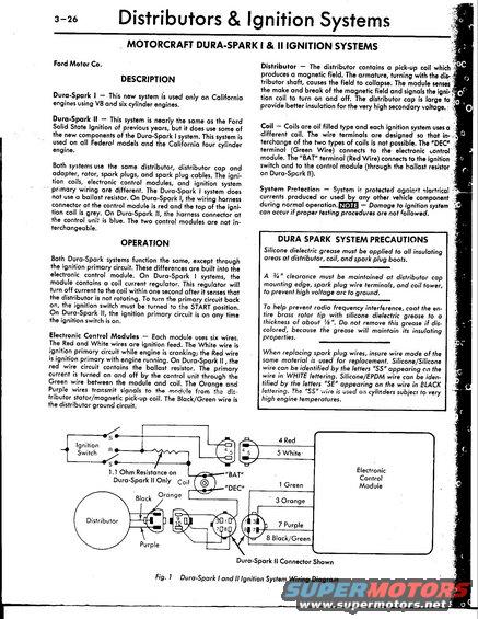
Ford Dura-Spark I/II ignition manual page (3-26): system description, operation, control module differences, silicone dielectric precautions, and Fig.1 connector wiring.
This page (3-26) from an automotive service manual covers the Motorcraft Dura-Spark I and II ignition systems used by Ford Motor Co. It explains that Dura-Spark I is used only on California V8 and six-cylinder engines, while Dura-Spark II is used on all Federal models and the California four-cylinder engine. Both systems share the same distributor, cap, adapter, rotor, spark plugs, and cables, but differ in coils, electronic control modules, and primary wiring; Dura-Spark I uses no ballast resistor (red module connector, grey coil top) while Dura-Spark II uses a blue connector and a 1.1-ohm ballast resistance. The Operation section details module wire functions: Red and White wires are ignition feed (White while cranking, Red while running), Green connects module to coil, Orange and Purple carry distributor stator/pick-up signals, and Black/Green is distributor ground. Sections on the distributor, oil-filled coils (BAT and DEC terminals), and system protection follow. A boxed 'Dura Spark System Precautions' section covers silicone dielectric grease application, maintaining 3/4-inch clearance to prevent arcing, coating the rotor tip 1/8-inch thick against RF interference, and identifying SS (Silicone/Silicone) vs SE (Silicone/EPDM) spark plug wires. Figure 1 is a full wiring diagram showing the ignition switch, ballast resistance, coil, distributor, connector pin numbers, and module wire colors.
Is this accurate? Sign in to help verify it.
Frequently asked questions
- What is the difference between Dura-Spark I and Dura-Spark II?
- Dura-Spark I is used only on California V8 and six-cylinder engines and has no ballast resistor, with a red harness connector at the module and a grey coil top. Dura-Spark II is used on all Federal models and the California four-cylinder engine, uses a ballast resistor (1.1 ohm), and has a blue connector at the control unit. The two control modules are not interchangeable.
- What do the wire colors on the Dura-Spark electronic control module mean?
- Red and White are ignition feed (White is ignition primary while cranking, Red is ignition primary with engine running), Green connects the module to the coil, Orange and Purple carry signals from the distributor stator/magnetic pick-up coil, and Black/Green is the distributor ground circuit.
- Which coil terminal connects to the electronic control module?
- The 'DEC' terminal (Green Wire) connects to the electronic control module. The 'BAT' terminal (Red Wire) connects to the ignition switch and to the control module (through the ballast resistor on Dura-Spark II).
- What precautions apply to the Dura-Spark system?
- Apply silicone dielectric grease to all insulating areas at the distributor, coil, and spark plug boots; maintain 3/4" clearance at the distributor cap mounting edge, spark plug wire terminals, and coil tower; coat the brass rotor tip with about 1/8" of silicone dielectric grease to prevent RF interference; and replace spark plug wires with the same material ('SS' silicone/silicone in white lettering, 'SE' silicone/EPDM in black lettering).
- Does the Dura-Spark II system use a ballast resistor?
- Yes. The red wire circuit on Dura-Spark II contains the ballast resistor, shown in the diagram as a 1.1 ohm resistance used on Dura-Spark II only. Dura-Spark I does not use a ballast resistor.
Comments
More from this build
No comments yet.