1993 Ford Festiva Intake & ISC-BPA Valve Diagram - Air Flow Meter, Throttle Body

Reference · 1988-1993 FestivaAll 2 schematics
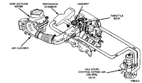
Schematic of the engine air intake system labeling the air flow meter, resonance chamber, throttle body and idle speed control valve.
Part of 1988-1993 Ford Festiva Schematics
This document is a labeled line-art schematic of the air intake and idle speed control system for a fuel-injected engine, uploaded as applying to a 1993 Ford Festiva. The illustration shows the intake tract components in their installed positions on the engine: the vane air flow meter mounted atop the air cleaner assembly, a corrugated intake hose leading through a resonance chamber to the throttle body, a dashpot mounted near the throttle body, and an idle speed control bypass air (ISC-BPA) valve located at the lower right, connected by a bypass hose routed from the throttle body area with flow-direction arrows. Six components are called out with arrows: vane air flow meter, resonance chamber, dashpot, throttle body, air cleaner, and the ISC-BPA valve. The figure carries the illustration reference number V7849-C. A reader can learn the identification, relative location, and hose routing of the intake/idle air control components, which is useful for diagnosing idle problems, locating the ISC-BPA valve for cleaning or replacement, or reassembling the intake system. The document contains no torque values, part numbers, wire colors, or year/model statements beyond the illustration code.
Is this accurate? Sign in to help verify it.
Frequently asked questions
- Where is the ISC-BPA (Idle Speed Control Bypass Air) valve located on this engine?
- Per the diagram, the ISC-BPA valve is mounted low on the right side of the engine, connected by a bypass air hose routed from the throttle body area, with arrows showing the direction of airflow.
- What components are shown in this intake schematic?
- The diagram labels the vane air flow meter, resonance chamber, dashpot, throttle body, air cleaner, and the idle speed control bypass air (ISC-BPA) valve.
- Where is the vane air flow meter located?
- The vane air flow meter sits on top of the air cleaner assembly, upstream of the corrugated intake hose that leads toward the resonance chamber and throttle body.
- What is the illustration reference number on this diagram?
- The figure is marked V7849-C in the lower right corner.
- Where is the dashpot in relation to the throttle body?
- The dashpot is shown mounted directly adjacent to (just above/beside) the throttle body.



No comments yet.