Home/
Registry/
Ford/
E-350 Econoline/
1992-2014/
“Angel Hauler”/
Photo
supermotors.net/registry/media/293983
Onboard Air Compressor System Plumbing Diagram - OBA Setup Schematic

Reference · 1992-2014 E-350 EconolineAll 1 schematics
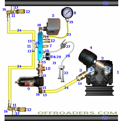
Technical schematic of an onboard air system with numbered callouts for compressor, tank, pressure gauge, regulator and air-line fittings.
Part of 1992-2014 Ford E-350 Econoline Schematics
This is a pictorial onboard air (OBA) system plumbing schematic hosted with an OFFROADERS.COM watermark. It shows how to plumb an engine-driven air compressor (converted A/C-style compressor with belt pulley) into a complete onboard air system. Components are identified only by numbered callouts (1 through 28); no text legend is included on this image, so the key presumably appears on a companion page. Visible elements include the belt-driven compressor with pulley, a pressure switch, a pressure gauge, a manifold block with multiple brass fittings, an inline filter/oiler-style canister, yellow air supply lines routing between components, quick-connect couplers at both ends of the system, a coiled hose with tire inflation chuck, and what appear to be air storage tanks represented by strips at the top and bottom of the diagram (labeled 25). A reader can learn the general plumbing layout and flow path of a DIY onboard air setup, from compressor output through pressure switch, gauge, manifold, filter, and out to air tanks and quick-disconnect service fittings, but component names, part numbers, and specifications are not stated on this page. The diagram is generic and not tied to any specific vehicle year, make, or model.
Is this accurate? Sign in to help verify it.
Frequently asked questions
- What does this onboard air diagram show?
- It is a pictorial plumbing schematic of an onboard air system, showing a belt-driven compressor, pressure switch, pressure gauge, manifold with brass fittings, an inline canister (filter/oiler), yellow air lines, quick-connect couplers, a tire inflation chuck, and air tank connections, all identified by numbered callouts 1-28.
- Does the diagram include a parts legend or part numbers?
- No. Components are marked only with numbers (1 through 28); no legend, part names, or part numbers are printed on this image.
- How are the air lines represented in the diagram?
- The air lines are shown as yellow tubing runs labeled with the number 24, connecting the compressor, manifold, filter canister, and the fittings at the top and bottom of the diagram.
- Is this diagram specific to a particular vehicle?
- No. The diagram shows no year, make, or model information; it is a generic onboard air system layout.





No comments yet.