Home/
Registry/
Ford/
LTD Crown Victoria/
1980-1982/
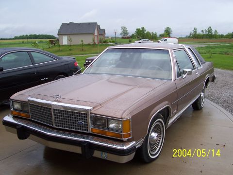
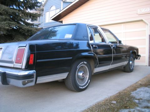
“Teh LTD”/
Photo
supermotors.net/registry/media/308106
Ford CD Changer Wiring Diagram - Fuses, Connector Pinout & Wire Colors

Reference · 1980-1982 LTD Crown VictoriaAll 3 wiring diagrams
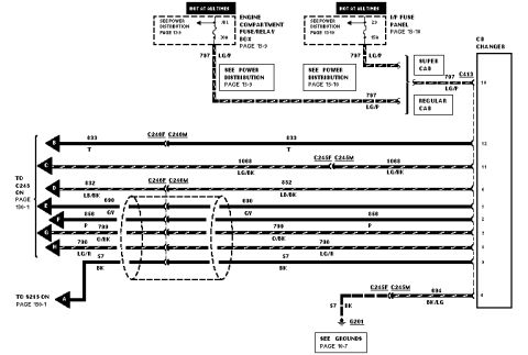
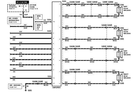
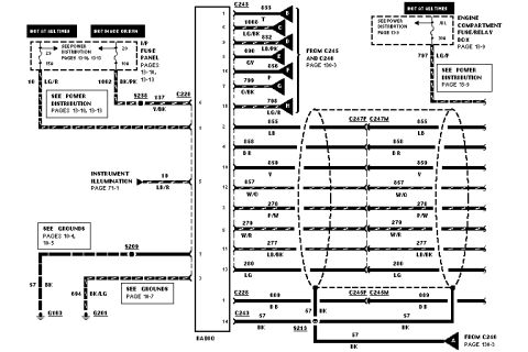
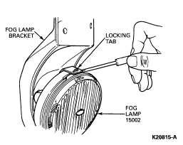
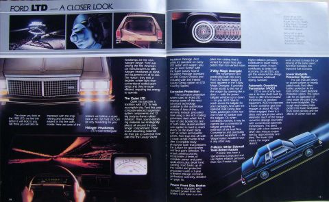
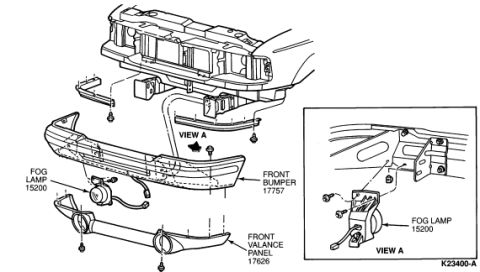
Wiring diagram of the CD changer circuit with color-coded conductors, connector callouts and power-distribution references.
Part of 1980-1982 Ford LTD Crown Victoria Wiring Diagrams
This document is one page of a Ford factory-style wiring diagram (EVTM format) covering the CD changer circuit. It shows power feeds from two sources, both hot at all times: fuse 18L (30A) in the engine compartment fuse/relay box (power distribution page 13-9) and fuse 23 (15A) in the instrument panel fuse panel (power distribution page 13-10), both feeding circuit 797 (LG/P wire). Separate routing is shown for Super Cab and Regular Cab configurations, with connector C413 delivering power to CD changer pin 10. The diagram details the CD changer connector pinout: audio and control circuits 833 (T), 1068 (LG/BK), 832 (LB/BK), 690, 856 (GY), 799 (P), 798 (O/BK), and 57 (BK), many routed through inline connectors C246F/C246M and C245F/C245M and through a shielded/twisted cable bundle, continuing to connector C243 on page 130-1. Ground circuit 57 (BK) goes to splice S213 (page 130-1) and to ground G201 via circuit 694 (BK/LG); grounds are detailed on page 10-7. A reader can learn the fuse locations and amperages, wire colors, connector identities, pin numbers, and cross-reference pages for the CD changer wiring.
Is this accurate? Sign in to help verify it.
Frequently asked questions
- What fuses power the CD changer in this diagram?
- Two hot-at-all-times feeds: fuse 18L (30A) in the engine compartment fuse/relay box (page 13-9) and fuse 23 (15A) in the I/P fuse panel (page 13-10), both on circuit 797 with a LG/P wire.
- What wire color is the CD changer constant power circuit?
- Circuit 797, light green/purple (LG/P), feeding CD changer pin 10 through connector C413.
- Where does the CD changer ground?
- Circuit 57 (BK) goes to splice S213 (page 130-1) and circuit 694 (BK/LG) from pin 4 goes through connectors C245F/C245M to circuit 57 (BK) and ground G201 (see grounds page 10-7).
- Which connectors are in the CD changer harness?
- C413 (power feed), inline connectors C246F/C246M and C245F/C245M, and the circuits continue to C243 on page 130-1.
- Does the wiring differ by cab type?
- Yes, the diagram shows separate 797 LG/P power routing for Super Cab and Regular Cab configurations.
No comments yet.